Mitsubishi Grandis. Manual - part 843


  Index      Mitsubishi     Mitsubishi Grandis - service repair manual


Search            


Content   ..  841  842  843  844   ..


Mitsubishi Grandis. Manual - part 843


TROUBLESHOOTING <A/T>

AUTOMATIC TRANSMISSION (FF)

23A-39

STEP 5. Connector check: C-112 engine-A/T-ECU 
connector

Check for the contact with terminals.

Q: Is the check result normal?

YES : 

Go to Step 6.

NO : 

Repair the defective connector.

STEP 6. MUT-III data list

Item 0002: Output shaft speed sensor (Refer to data 
list reference table 

P.23A-117

). 

Q: Is the check result normal?

YES : 

Intermittent malfunction (Refer to GROUP 

00 

− How to Cope with Intermittent 

Malfunction 

P.00-5

).

NO : 

Replace the engine-A/T-ECU.

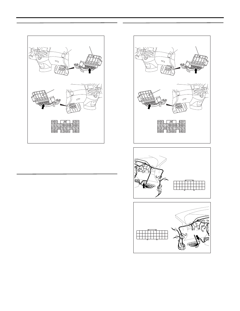
STEP 7. Connector check: C-112 engine-A/T-ECU 
connector, C-116 J/C (4)

Check for the contact with terminals.

Q: Is the check result normal?

YES : 

Go to Step 8.

NO : 

Repair the defective connector.

AC311284

Connector: C-112 <LHD>

Connector: C-112 <RHD>

Harness side

Engine-A/T-ECU

C-112 (GR)

C-112 (GR)

Engine-A/T-ECU

AG

AC311284

Connector: C-112 <LHD>

Connector: C-112 <RHD>

Harness side

Engine-A/T-ECU

C-112 (GR)

C-112 (GR)

Engine-A/T-ECU

AG

AC310615

C-116

Connector: C-116
<LHD>

AP

23

12

1

7

29

18

4

26

15

1314

25

24

2 3

1617

28

27

5 6

10

32

21

1920
3031

8 9

22
33

11

AC310628AS

C-116

Connector: C-116
<RHD>

23

12

1

7

29

18

26

13

25

24

2

28

27

4

15

14

3

1617

5 6

10

32

21

1920
3031

8 9

22
33

11

TROUBLESHOOTING <A/T>

AUTOMATIC TRANSMISSION (FF)

23A-40

STEP 8. Check the harness between output shaft 
speed sensor connector B-108 terminal No.1 and 
engine-A/T-ECU connector C-112 terminal No.88.

Check the earth line for open circuit.

Q: Is the check result normal?

YES : 

Go to Step 6.

NO : 

Repair the wiring harness.

STEP 9. Measure the voltage at output shaft 
speed sensor connector B-108.

(1) Disconnect the connector, and measure the 

voltage between terminal 3 and earth at the 
wiring harness side.

(2) Turn the ignition switch to the ON position.

OK: System voltage

Q: Is the check result normal?

YES : 

Go to Step 12.

NO : 

Go to Step 10.

AC302452AH

B-108 (GR)

Connector: B-108

Harness side

AC311284

Connector: C-112 <LHD>

Connector: C-112 <RHD>

Harness side

Engine-A/T-ECU

C-112 (GR)

C-112 (GR)

Engine-A/T-ECU

AG

AC302452AH

B-108 (GR)

Connector: B-108

Harness side

TROUBLESHOOTING <A/T>

AUTOMATIC TRANSMISSION (FF)

23A-41

STEP 10. Connectors check: C-203 J/B 
connector, C-18 intermediate connector, C-116 
J/C (4), C-33 J/C (7) <RHD>

TROUBLESHOOTING <A/T>

AUTOMATIC TRANSMISSION (FF)

23A-42

Check for the contact with terminals.

Q: Is the check result normal?

YES : 

Go to Step 11.

NO : 

Repair the defective connector.

AC310623

Connectors: C-203 <LHD>

AL

Harness side

10

1

6

14

5

12

13

4

11

7

2

3

8

9

Junction block (Front view)

AC310618

Connectors: C-203 <RHD>

AK

Harness side

10

1

6

14

5

12

13

4

11

7

2

3

8

9

Junction block (Front view)

AC310615

AQ

Connector: C-18
<LHD>

C-18

2

6

1

5

9

3

7 8

10

4

AC310628

C-18

AC310628AT

Connector: C-18
<RHD>

C-18

2

6

1

5

9

3

7 8

10

4

AC310615

C-116

Connector: C-116
<LHD>

AP

23

12

1

7

29

18

4

26

15

1314

25

24

2 3

1617

28

27

5 6

10

32

21

1920
3031

8 9

22
33

11

AC310628AS

C-116

Connector: C-116
<RHD>

23

12

1

7

29

18

26

13

25

24

2

28

27

4

15

14

3

1617

5 6

10

32

21

1920
3031

8 9

22
33

11

AC310631AV

C-33

Connector: C-33
<RHD>

2

1

3

13

12

14

21

10

5

4

6

16

15

17

7 8 9

19

18

20

11

22


Content   ..  841  842  843  844   ..