Mitsubishi Grandis. Manual - part 844
TROUBLESHOOTING <A/T>
AUTOMATIC TRANSMISSION (FF)
23A-43
STEP 11. Check the harness between output
shaft speed sensor connector B-108 terminal
No.3 and junction block connector C-203
terminal No.12.
Check the power supply line for short or open circuit.
Q: Is the check result normal?
YES :
Go to Step 6.
NO :
Repair the wiring harness.
STEP 12. Measure the voltage at output shaft
speed sensor connector B-108.
(1) Disconnect the connector, and measure the
voltage between terminal 2 and earth at the
wiring harness side.
(2) Turn the ignition switch to the ON position.
OK: 4.9
− 5.1 V
Q: Is the check result normal?
YES :
Go to Step 18.
NO :
Go to Step 13.
STEP 13. Measure the voltage at engine-A/T-ECU
connector C-112.
(1) Disconnect output shaft speed sensor connector
B-108.
(2) Turn the ignition switch to the ON position.
(3) Measure the voltage between engine-A/T-ECU
connector C-112 terminal No.73 and earth.
OK: 4.9
− 5.1 V
Q: Is the check result normal?
AC302452AH
B-108 (GR)
Connector: B-108
Harness side
AC310623
Connectors: C-203 <LHD>
AL
Harness side
10
1
6
14
5
12
13
4
11
7
2
3
8
9
Junction block (Front view)
AC310618
Connectors: C-203 <RHD>
AK
Harness side
10
1
6
14
5
12
13
4
11
7
2
3
8
9
Junction block (Front view)
AC302452AH
B-108 (GR)
Connector: B-108
Harness side
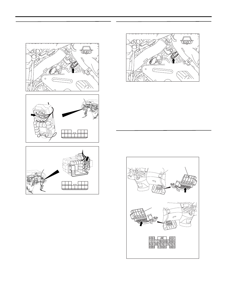
AC311284
Connector: C-112 <LHD>
Connector: C-112 <RHD>
Harness side
Engine-A/T-ECU
C-112 (GR)
C-112 (GR)
Engine-A/T-ECU
AG