Mitsubishi Grandis. Manual - part 814
SPECIAL TOOL
POWER PLANT MOUNT
32-3
SPECIAL TOOL
M1321000600453
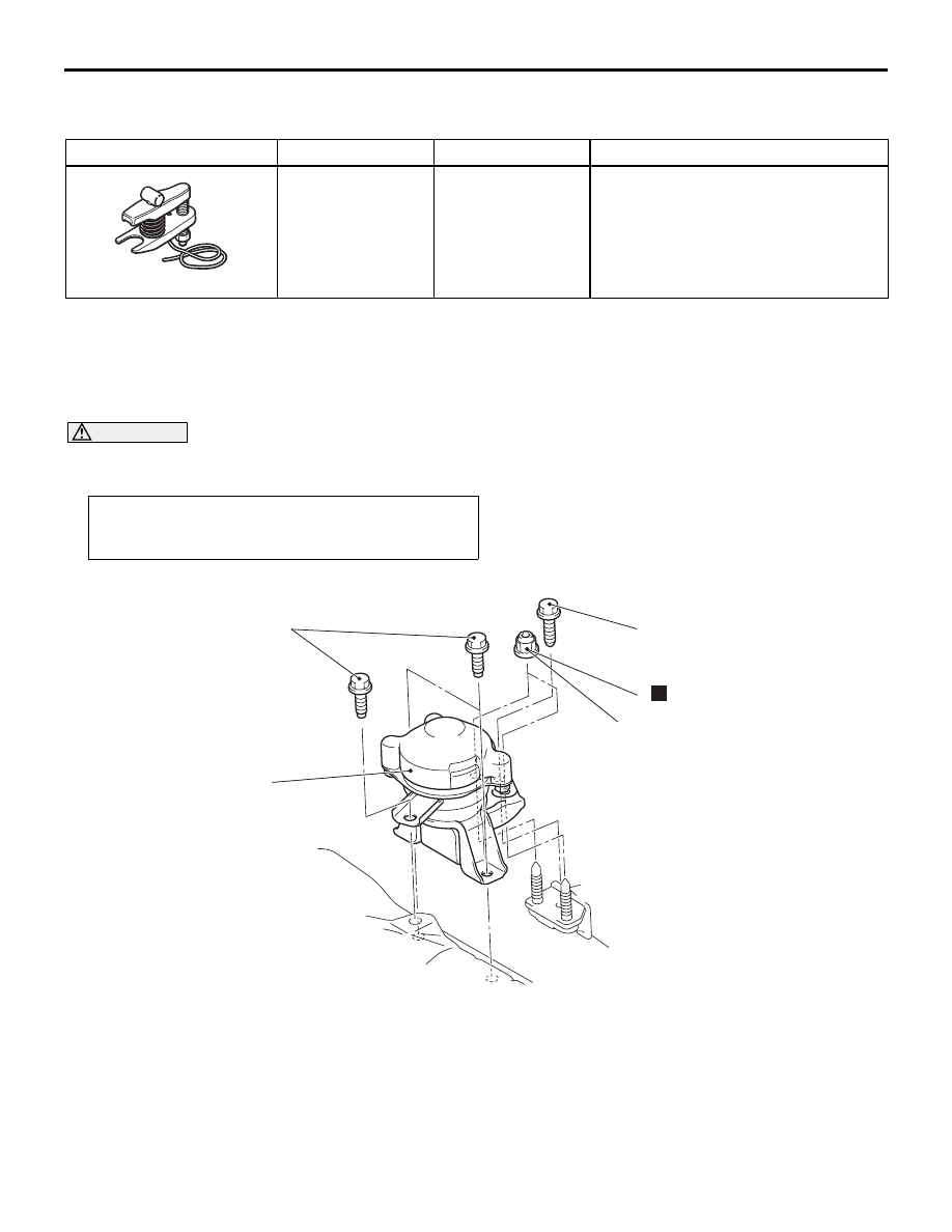
ENGINE MOUNTING
REMOVAL AND INSTALLATION
M1321001100611
CAUTION
*: Indicates parts which should be initially tightened, and then fully tightened after placing the vehicle
horizontally and loading the full weight of the engine on the vehicle body.
Tool
Number
Name
Use
MB991897
Ball joint remover
Knuckle and tie rod end ball joint
disconnection
NOTE: Steering linkage puller
(MB990635 or MB991113) is also
available to disconnect knuckle and
tie rod end ball joint.
AC106827
Pre-removal Operation
Raise the engine and transmission assembly until its weight
is not applied to the insulator, and support it securely.
AC302098
1
2
78 ± 7 N·m
78 ± 7 N·m*
78 ± 7 N·m*
N
AC
Removal steps
1.
Self-locking nuts
2.
Engine front mounting bracket