Mitsubishi Grandis. Manual - part 813
RADIATOR
ENGINE COOLING
14-25
RADIATOR
REMOVAL AND INSTALLATION
M1141001500628
Pre-removal and Post-installation Operation
• Engine Coolant Draining and Supplying (Refer to
• Air Cleaner Assembly Removal and Installation (Refer to
GROUP 15
).
AC310381
1
2
3
4
4
8
9
13
12
7
15
10
17
14
14
5
6
6
20
23
16
22
21
19
18
11
21 ± 4 N·m
12 ± 2 N·m
N
N
N
N
AB
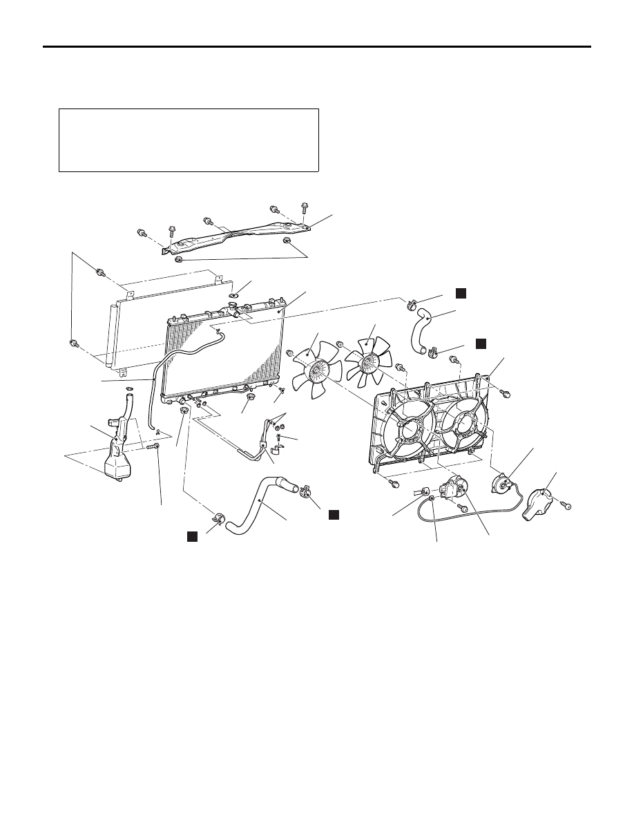
Radiator removal steps
1.
Drain plug
2.
Radiator cap
<<A>>
>>A<<
3.
Radiator upper hose
<<A>>
>>A<<
4.
Hose clips
<<A>>
>>A<<
5.
Radiator lower hose
<<A>>
>>A<<
6.
Hose clips
7.
A/T oil cooler hose connection
<A/T>
8.
Front end upper bar
9.
Radiator support upper insulator
10. Radiator condenser tank hose
11. Fan controller connector
<<B>>
12. A/C condenser connecting bolts
13. Radiator assembly
14. Radiator support lower insulator
15. A/T oil cooler hose <A/T>
16. Cooling fan motor and shroud
assembly
17. Radiator condenser tank assembly
18. Condenser fan motor connector
19. Cooling fan motor and fan
controller
20. Cooling fan
21. Cooling fan protector
22. Condenser fan motor
23. Condenser fan
Radiator condenser tank removal
steps
10. Radiator condenser tank hose
11. Fan controller connector
8.
Front end upper bar
Radiator removal steps