Mitsubishi Grandis. Manual - part 792


  Index      Mitsubishi     Mitsubishi Grandis - service repair manual


Search            


Content   ..  790  791  792  793   ..


Mitsubishi Grandis. Manual - part 792


AUTO-CRUISE CONTROL

ENGINE AND EMISSION CONTROL

17-9

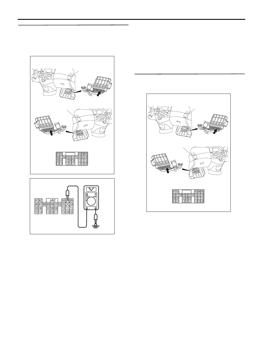
STEP 3. Measure the voltage at engine-ECU 
connector C-113 <M/T> or engine-A/T-ECU 
connector C-113 <A/T>.
(1) Turn the ignition switch to the "ON" position and 

the MAIN switch to the "OFF" position.

(2) Measure the voltage between engine-ECU 

connector C-113 <M/T> terminal No.94 or 
engine-A/T-ECU connector C-113 <A/T> terminal 

No.94 and earth.

OK: 4.7

5.0 V

(3) Turn the ignition switch to the "LOCK" (OFF) 

position.

Q: Is the check result normal?

YES : 

Go to Step 6.

NO : 

Go to Step 4.

STEP 4. Connector check: C-113 engine-ECU 
connector <M/T> or C-113 engine-A/T-ECU 
connector <A/T>

Q: Is the check result normal?

YES : 

Go to Step 5.

NO : 

Repair or replace the faulty connector, and 
install the air bag module (driver’s side) 
(Refer to GROUP 52B,  Driver’s, Front 
Passenger’s Air Bag Module(s) and Clock 
Spring 

P.52B-225

). Then go to Step 18.

AC311284AC

Connector: C-113

<L.H. drive vehicles>

<R.H. drive vehicles>

C-113 (GR)

C-113 (GR)

AC304572AE

C-113 harness 
connector: 
harness side

AC311284AC

Connector: C-113

<L.H. drive vehicles>

<R.H. drive vehicles>

C-113 (GR)

C-113 (GR)

AUTO-CRUISE CONTROL

ENGINE AND EMISSION CONTROL

17-10

STEP 5. Check the harness between engine-ECU 
connector C-113 <M/T> terminal No.94 or 
engine-A/T-ECU connector C-113 <A/T> terminal 
No.94 and the auto-cruise control switch 
connector C-305 terminal No.2.

(1) Disconnect engine-ECU connector C-113 <M/T> 

or engine-A/T-ECU connector C-113 <A/T> and 

measure at the harness connector side.

(2) Turn the ignition switch to the "ON" position and 

the MAIN switch to the "OFF" position.

(3) Measure the continuity between engine-ECU 

connector C-113 <M/T> terminal No.94 or 
engine-A/T-ECU connector C-113 <A/T> terminal 
No.94 and earth.

(4) Turn the ignition switch to the "LOCK" (OFF) 

position.

(5) Connect engine-ECU connector C-113 <M/T> or 

engine-A/T-ECU connector C-113 <A/T>.

Q: Is the measured continuity open circuit?

YES : 

Install the air bag module (driver’s side) 

(Refer to GROUP 52B,  Driver’s, Front 
Passenger’s Air Bag Module(s) and Clock 
Spring 

P.52B-225

). Then go to Step 17.

NO : 

Go to Step 6.

AC311284AC

Connector: C-113

<L.H. drive vehicles>

<R.H. drive vehicles>

C-113 (GR)

C-113 (GR)

AC304573AE

C-113 harness 
connector: 
component side

AUTO-CRUISE CONTROL

ENGINE AND EMISSION CONTROL

17-11

STEP 6. Connectors check: C-305 auto-cruise 
control switch connector, C-17 and C-304 
intermediate connectors, C-310 and C-311 clock 
spring connectors

Q: Is the check result normal?

AC311914AE

C-17

Connector: C-17 
<L.H. drive vehicles>

AC311915AF

C-17

Connector: C-17 
<R.H. drive vehicles>

AC311366

C-304

C-305

C-310

C-311

Connectors: C-304, C-305, C-310, C-311

<L.H. drive vehicles>

<R.H. drive vehicles>

C-311

C-310 (B)

C-310 (B)

C-311

AB

Clock
spring

Clock
spring

C-305 (Y)

C-304 (B)

C-305 (Y)

C-304 (B)

AUTO-CRUISE CONTROL

ENGINE AND EMISSION CONTROL

17-12

YES : 

Go to Step 7.

NO : 

Repair or replace the faulty connector, and 
install the air bag module (driver’s side) 
(Refer to GROUP 52B,  Driver’s, Front 
Passenger’s Air Bag Module(s) and Clock 
Spring 

P.52B-225

). Then go to Step 18.


Content   ..  790  791  792  793   ..