Mitsubishi Grandis. Manual - part 657


  Index      Mitsubishi     Mitsubishi Grandis - service repair manual


Search            


Content   ..  655  656  657  658   ..


Mitsubishi Grandis. Manual - part 657


TIMING BELT

ENGINE OVERHAUL

11B-23

2. Install special tool Sprocket stopper (MD998785) 

as shown in the illustration to lock the 
counterbalance shaft.

3. Tighten the bolt, and then remove the special tool.

Tightening torque: 45 

± 3 Nm

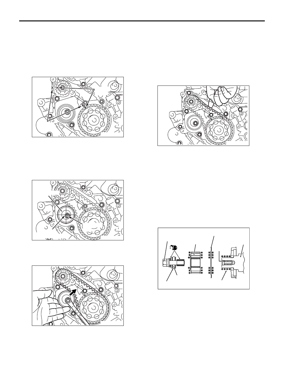
>>F<< TIMING BELT "B" INSTALLATION

1. Align timing marks on the crankshaft sprocket "B" 

and counterbalance shaft sprocket with the marks 
on the front case.

2. Install the timing belt "B" on the crankshaft 

sprocket "B" and counterbalance shaft sprocket. 
There should be no slack on the tension side.

3. Make sure that the tensioner pulley center and the 

bolt center are positioned as shown in the 
illustration.

4. Move tensioner "B" in the direction of the arrow 

while lifting with your finger to give sufficient 
tension to the tension side of timing belt. In this 
condition, tighten the bolt to secure tensioner "B." 
When the bolt is tightened, use care to prevent 
the tensioner pulley shaft from turning with the 
bolt. If the shaft is turned with the bolt, the belt will 
be over tensioned.

Tightening torque: 19 

± 3 Nm

5. Check that timing marks on the sprockets are 

aligned with the timing marks on the front case.

6. With your index finger, press the midway of span 

on the tension side of timing belt "B." The bolt 
must deflect 5 to 7 mm.

>>G<< CRANKSHAFT SENSING 
BLADE/CRANKSHAFT 
SPROCKET/CRANKSHAFT PULLEY 
WASHER/CRANKSHAFT BOLT 
INSTALLATION

1. Clean and then degrease the contacting surfaces 

of the crankshaft sprocket, sensing blade and 
crankshaft.
NOTE: Degreasing is necessary to prevent 
decrease in the friction between contacting 
surfaces.

2. Clean the bolt hole in the crankshaft, the 

crankshaft contacting surface of the crankshaft 
sprocket, and the washer.

AK300143

Timing
mark

Timing 
mark

AD

AK300144

Center of
tensioner pulley

Center of
bolt

Tensioner "B"

AD

AK300145

AK300146

AK301075AD

Crankshaft
bolt

Sprocket

Sensing blade

Clean

Crankshaft

Degrease

Washer

Big chamfered side

TIMING BELT

ENGINE OVERHAUL

11B-24

3. Install the sensing blade and the crankshaft 

sprocket to the crankshaft.

4. Apply a small amount of engine oil to the threads 

and seating surface of the crankshaft bolt.

5. Install the washer to the crankshaft bolt with the 

larger chamfered side toward the bolt head.

6. Using special tool Fly wheel stopper (MD998781), 

hold the drive plate.

7. Tighten the crankshaft bolt to the specified torque.

Tightening torque: 167 N

m

>>H<< OIL PUMP SPROCKET 
INSTALLATION

1. Insert a Phillips head screwdriver (shank diameter 

8 mm) through the plug hole on the left side of the 
cylinder block to block the left counterbalance 
shaft.

2. Install the oil pump sprocket.
3. Apply a thin coat of engine oil to the seating 

surface of the nut.

4. Tighten the nut to the specified torque.

Tightening torque: 54 

± 5 N

>>I<< AUTO-TENSIONER INSTALLATION

If the auto-tensioner rod is fully extended, reset it as 
follows:

1. Clamp the auto-tensioner in a vise with soft jaws.

2. Push in the rod little by little with the vise until the 

set hole A in the rod is aligned with hole B in the 
cylinder.

3. Insert a wire (1.4 mm in diameter) into the set 

holes. This auto-tensioner setting wire will be 
used during timing belt alignment.

4. Unclamp the auto-tensioner from the vise.

AK202738

MD998781

AD

<M/T>

AK300135

MD998781

AG

<A/T>

AK301073

AK300154

AK301074

A

B

AD

AK301832

TIMING BELT

ENGINE OVERHAUL

11B-25

CAUTION

Leave the wire installed in the auto-tensioner.
5. Install the auto-tensioner onto the front case and 

tighten to the specified torque.

Tightening torque: 23 

± 3 Nm

>>J<< TENSIONER PULLEY 
INSTALLATION

Set the tensioner pulley so that the holes for 
attaching a wrench may be positioned as shown in 
the illustration.

>>K<< TIMING BELT INSTALLATION

1. Align the timing mark on the camshaft sprocket 

with the timing mark on the rocker cover.

2. Align the timing mark on the crankshaft sprocket 

with the timing mark on the front case.

3. Align the timing mark on oil pump sprocket with its 

mating mark.

4. Remove the plug on the cylinder block and insert 

a Phillips head screwdriver (shank diameter 8 
mm) through the hole.
If it can be inserted as deep as 60 mm or more, 
the timing marks are correctly aligned.
If the inserted depth is only 20 to 25 mm, turn the 
oil pump sprocket one turn and realign the timing 
marks. Then check to ensure that the screwdriver 
can be inserted 60 mm or more. Keep the 
screwdriver inserted until the timing belt is 
completely installed.

5. Set the special tool Set screw (MD998738)  as 

shown and screw it in up to the position where the 
wire inserted in the auto-tensioner when installing 
it can be moved lightly.

6. Install the timing belt on the crankshaft sprocket, 

oil pump sprocket, idler pulley, camshaft sprocket, 
and tensioner pulley in that order.

AK300147AD

Tensioner 
pulley hole

AK300148

Timing mark

AD

AK300149

Timing mark

AD

AK301076AD

Timing mark

AK301077

60 mm or more

AD

Counter
balance
shaft

AK300151

MD998738

AD

TIMING BELT

ENGINE OVERHAUL

11B-26

7. Lift up the tensioner pulley in the direction of the 

arrow and tighten the center bolt. 

8. Check that all timing marks are aligned.
9. Remove the screwdriver inserted in step 5 and 

install the plug.

10.Turn the crankshaft a quarter turn 

counterclockwise. Then, turn it clockwise until the 
timing marks are aligned again.

11.Install special tool Tension pulley socket wrench 

(MD998767), socket wrench and torque wrench, 
onto the tensioner pulley, and loosen the 
tensioner pulley center bolt.
NOTE: Use a torque wrench that can measure 0 
to 5.0 N

m.

12.Torque to 3.5 N

⋅m with the torque wrench.

13.Holding the tensioner pulley with special tool 

Tension pulley socket wrench (MD998767) and 
torque wrench, tighten the center bolt to 
specification.

Tightening torque: 48 

± 5 N

14. The wire inserted at the auto-tensioner 

installation is pulled out and then the special tool 
Set screw (MD998738) is removed by hand.

15.Give two clockwise turns to the crankshaft. Wait 

for 15 minutes, then proceed with the following 
inspection steps.

16.Check to see whether the metal wire (inserted 

when the auto-tensioner was installed) can be 
removed without any resistance. If the metal wire 
can be removed without any resistance, it means 
that the belt has a proper tension. Therefore, 
remove the metal wire. In this condition, check 
that the rod protrusion of the auto-tensioner is 
within the standard value.

Standard value: 3.8 

 4.5 mm 

17.If the metal wire offers resistance when removed, 

repeat the previous steps 10 through 15 until the 
standard value is obtained as measured by the 
rod projection of the auto-tensioner rod.

AK301295AD

Auto tensioner

AK300150

MD998767

AD

AK301836

AK300152


Content   ..  655  656  657  658   ..