Mitsubishi Grandis. Manual - part 647
CHARGING SYSTEM
ENGINE ELECTRICAL
16-12
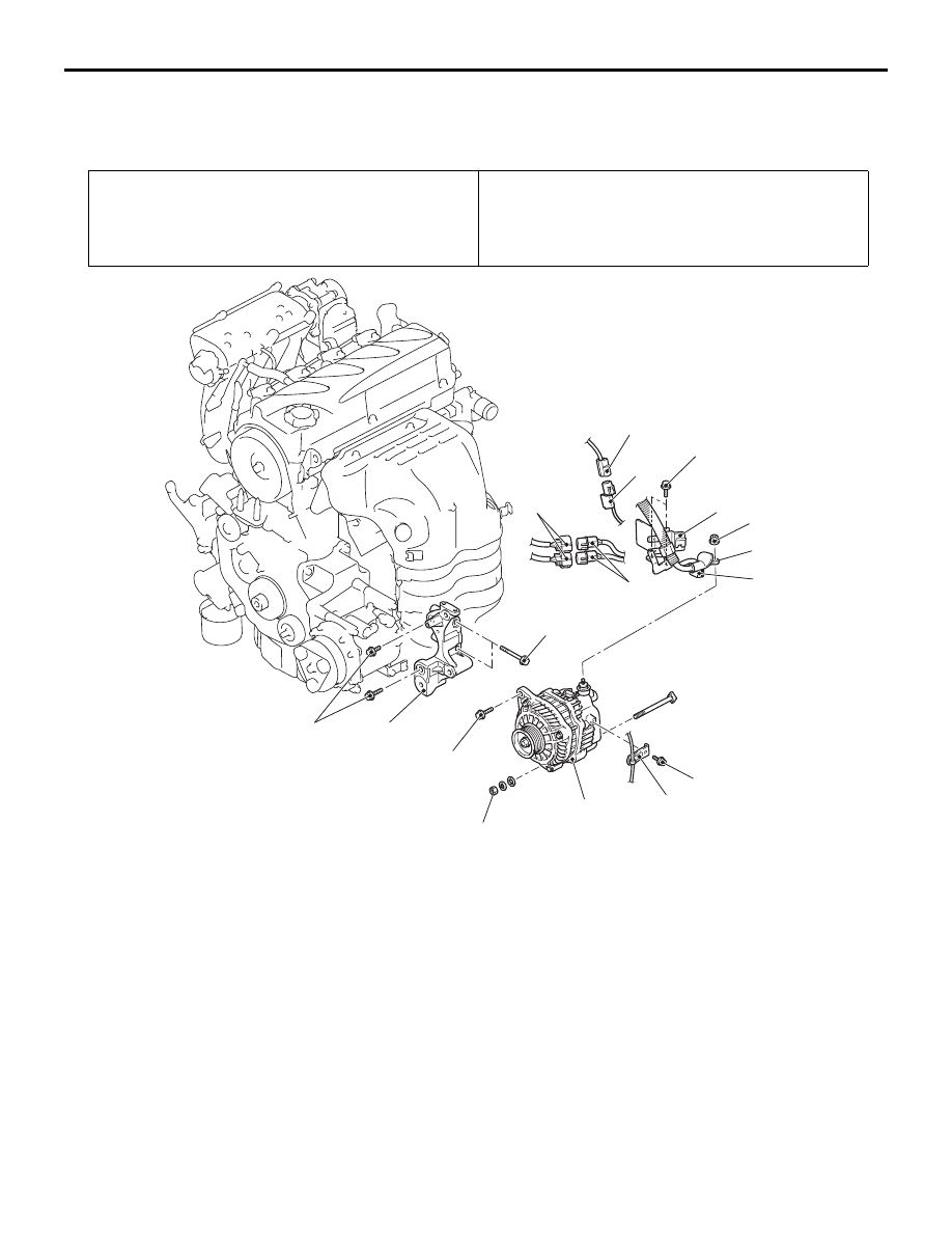
ALTERNATOR ASSEMBLY
REMOVAL AND INSTALLATION
M1161001400742
REMOVAL SERVICE POINT
<<A>> ALTERNATOR ASSEMBLY
REMOVAL
Remove the alternator assembly from above the
vehicle.
Pre-removal Operation
Drive Belt Removal (Refer to GROUP 11A, Crankshaft
Pulley
).
Post-installation Operation
• Drive Belt Installation (Refer to GROUP 11A, Crankshaft
Pulley
).
• Drive Belt Tension Check (Refer to GROUP 11A,
On-vehicle Service
).
AC313042
11 ± 1 N·m
11 ± 1 N·m
14 ± 3 N·m
1
6
5
3
7
4
9
8
10
AB
44 ± 10 N·m
49 ± 9 N·m
49 ± 9 N·m
2
49 ± 9 N·m
Removal steps
1.
Oxygen sensor connector
2.
Oxygen sensor connector clamp
3.
A/C compressor assembly
connector
4.
A/C compressor assembly
connector clamp
5.
Alternator connector
6.
Alternator terminal
7.
Connector bracket
8.
Harness clamp
<<A>>
9.
Alternator assembly
•
Timing belt lower cover (Refer to
GROUP 11A, Timing Belt
10. Alternator mounting bracket
Removal steps (Continued)