Mitsubishi Grandis. Manual - part 567
DIAGNOSIS
CONTROLLER AREA NETWORK (CAN)
54D-366
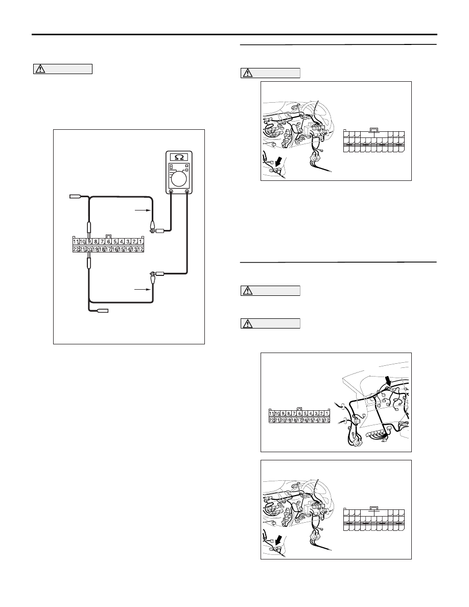
wiring harness side.
(2) Ignition switch: OFF (LOCK)
CAUTION
When measuring the resistance, disconnect the
negative battery terminal. For details refer to
(3) Ensure that the negative battery terminal is
disconnected.
(4) Resistance between C-09 joint connector (CAN2)
terminal Nos. 9 and 20
OK: 1 k
Ω or more
Q: Is the check result normal?
YES :
<1 k
Ω or more> Follow diagnostic item 19,
Diagnose CAN bus lines thoroughly. Refer
to
NO :
<Less than 1 k
Ω> Repair the wiring harness
between the joint connector (CAN2) and the
jumper connector.
STEP 20. Connector check: C-119 SRS-ECU
connector
CAUTION
The strand end of the twist wire should be within
10 cm from the connector. For details refer to
Q: Is the check result normal?
YES :
Go to Step 21.
NO :
Repair the defective connector.
STEP 21. Resistance measurement at C-09 joint
connector (CAN2).
CAUTION
A digital multimeter should be used. For details
refer to
.
CAUTION
The test wiring harness should be used. For
details refer to
(1) Disconnect the joint connector (CAN2) and the
SRS-ECU connector, and measure at the wiring
AC204740DP
Harness side: C-09
Test
harness
Test
harness
AC310631AZ
Connector: C-119 <RHD>
Harness side
C-119 (Y)
48
37
26
42
31
45
34
47
36
46
35
44
33
43
32
25 24
39
28
41
30
40
29
38
27
23
21
22
A
B
AC310628AY
Connector: C-09 <RHD>
C-09 (GR)
Harness side
AC310631AZ
Connector: C-119 <RHD>
Harness side
C-119 (Y)
48
37
26
42
31
45
34
47
36
46
35
44
33
43
32
25 24
39
28
41
30
40
29
38
27
23
21
22
A
B