Mitsubishi Grandis. Manual - part 566
DIAGNOSIS
CONTROLLER AREA NETWORK (CAN)
54D-362
STEP 11. Connector check: C-221 ETACS-ECU
connector
CAUTION
The strand end of the twist wire should be within
10 cm from the connector. For details refer to
Q: Is the check result normal?
YES :
Go to Step 12.
NO :
Repair the defective connector.
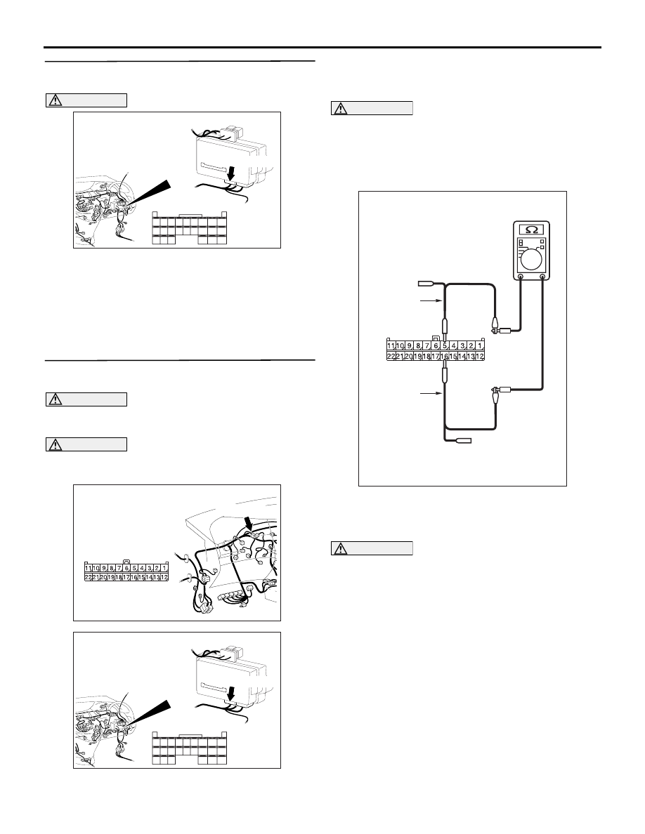
STEP 12. Resistance measurement at C-09 joint
connector (CAN2).
CAUTION
A digital multimeter should be used. For details
refer to
CAUTION
The test wiring harness should be used. For
details refer to
(1) Disconnect the joint connector (CAN2) and the
ETACS-ECU connector, and measure at the
wiring harness side.
(2) Ignition switch: OFF (LOCK)
CAUTION
When measuring the resistance, disconnect the
negative battery terminal. For details refer to
(3) Ensure that the negative battery terminal is
disconnected.
(4) Continuity between C-09 joint connector (CAN2)
terminal Nos. 5 and 16
OK: More than 2
Ω
CAUTION
Strictly observe the specified wiring harness
repair procedure. For details refer to
Q: Is the check result normal?
YES :
<More than 2
Ω> Go to Step 13.
NO :
<2
Ω or less> Repair the wiring harness
between joint connector (CAN2) and the
ETACS-ECU connector.
AC310620
Connector: C-221
Junction block
(Rear view)
<RHD>
AC
51
52
53
54
55
56
57
58
59
60
61
62
63
64
65
66
67
68
69
70
71
72
73
74
Harness side
C-221(GR)
AC310628AY
Connector: C-09 <RHD>
C-09 (GR)
Harness side
AC310620
Connector: C-221
Junction block
(Rear view)
<RHD>
AC
51
52
53
54
55
56
57
58
59
60
61
62
63
64
65
66
67
68
69
70
71
72
73
74
Harness side
C-221(GR)
AC204740DG
Harness side: C-09
Test
harness
Test
harness