Mitsubishi Grandis. Manual - part 539


  Index      Mitsubishi     Mitsubishi Grandis - service repair manual


Search            


Content   ..  537  538  539  540   ..


Mitsubishi Grandis. Manual - part 539


DIAGNOSIS

CONTROLLER AREA NETWORK (CAN)

54D-254

YES : 

Go to Step 26.

NO : 

Repair the defective connector.

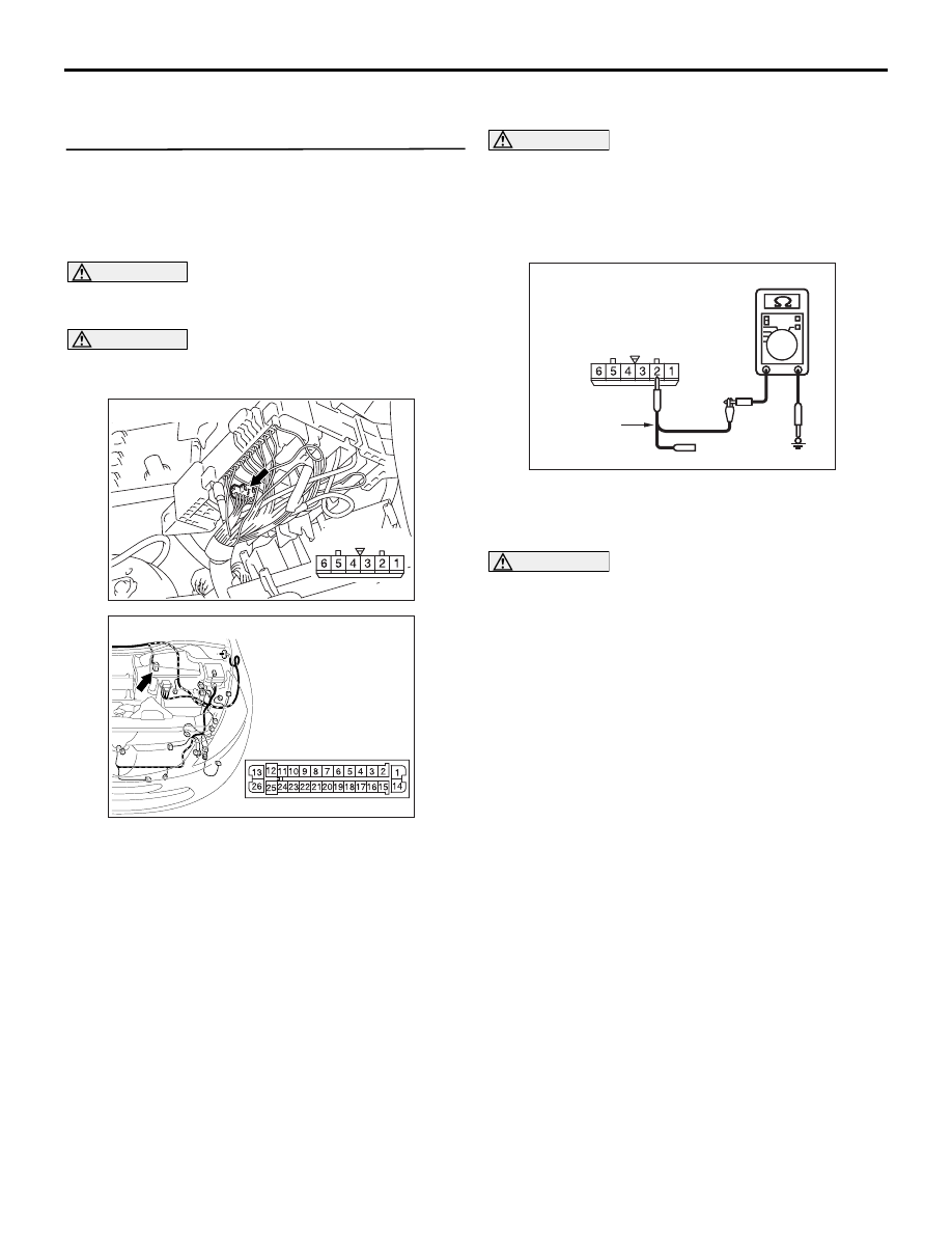
STEP 26. Resistance measurement at the A-07 
joint connector (CAN1).
NOTE: When checking A-07 joint connector (CAN1), 
disassemble and check the engine compartment 
relay box by referring to 

P.54D-616

.

CAUTION

A digital multimeter should be used. For details 
refer to 

P.54D-8

.

CAUTION

The test wiring harness should be used. For 
details refer to 

P.54D-8

.

(1) Disconnect the joint connector (CAN1) and the 

ABS-ECU connector, and measure at the wiring 
harness side.

CAUTION

When measuring the resistance, disconnect the 
negative battery terminal. For details refer to 

P.54D-8

.

(2) Ensure that the negative battery terminal is 

disconnected.

(3) Resistance between A-07 joint connector (CAN1) 

terminal No.2 and body earth

OK: 1 k

 or more

CAUTION

Strictly observe the specified wiring harness 
repair procedure. For details refer to 

P.54D-8

.

Q: Is the check result normal?

YES : 

<1 k

Ω or more> Follow diagnostic item 19, 

Diagnose CAN bus lines thoroughly. Refer 
to 

P.54D-502

.

NO : 

<less than 1 k

Ω> Repair the wiring harness 

between the joint connector (CAN1) and the 
ABS-ECU connector.

AC302572AD

Connector: A-07

Harness side

AC310398

AI

Connector: A-03 <RHD>

Harness side

AC209364

Harness side: A-07

AC209364LO

Test
harness

DIAGNOSIS

CONTROLLER AREA NETWORK (CAN)

54D-255

STEP 27. Resistance measurement at the A-07 
joint connector (CAN1).
NOTE: When checking A-07 joint connector (CAN1), 
disassemble and check the engine compartment 
relay box by referring to 

P.54D-616

.

CAUTION

A digital multimeter should be used. For details 
refer to 

P.54D-8

.

CAUTION

The test wiring harness should be used. For 
details refer to 

P.54D-8

.

(1) Disconnect the joint connector (CAN1) and the 

intermediate connector, and measure at the 
wiring harness side.

CAUTION

When measuring the resistance, disconnect the 
negative battery terminal. For details refer to 

P.54D-8

.

(2) Ensure that the negative battery terminal is 

disconnected.

(3) Resistance between A-07 joint connector (CAN1) 

terminal No.1 and body earth

OK: 1 k

 or more

CAUTION

Strictly observe the specified wiring harness 
repair procedure. For details refer to 

P.54D-8

.

Q: Is the check result normal?

YES : 

<1 k

Ω or more> Follow diagnostic item 19, 

Diagnose CAN bus lines thoroughly. Refer 
to 

P.54D-502

.

NO : 

<less than 1 k

Ω> Repair the wiring harness 

between the joint connector (CAN1) and the 
intermediate connector.

STEP 28. Connector check: C-125 intermediate 
connector

CAUTION

The strand end of the twist wire should be within 
10 cm from the connector. For details refer to 

P.54D-8

.

Q: Is the check result normal?

YES : 

Go to Step 29.

NO : 

Repair the defective connector.

AC302572AD

Connector: A-07

Harness side

AC310628AB

Connector: C-125 <RHD>

AC209364

AC209364

AC209364

AC209364

Harness side: A-07

AC209364LQ

Test
harness

AC310628AB

Connector: C-125 <RHD>

DIAGNOSIS

CONTROLLER AREA NETWORK (CAN)

54D-256

STEP 29. Resistance measurement at the C-125 
intermediate connector.

CAUTION

A digital multimeter should be used. For details 
refer to 

P.54D-8

.

CAUTION

The test wiring harness should be used. For 
details refer to 

P.54D-8

.

(1) Disconnect the connector, and measure at its 

male-side intermediate connector (at the front 
wiring harness side).

CAUTION

When measuring the resistance, disconnect the 
negative battery terminal. For details refer to 

P.54D-8

.

(2) Ensure that the negative battery terminal is 

disconnected.

(3) Resistance between C-125 intermediate 

connector terminal No.26 and body earth

OK: 1 k

 or more

Q: Is the check result normal?

YES : 

<1 k

Ω or more> Go to Step 30.

NO : 

<less than 1 k

Ω> Go to Step 45.

STEP 30. Connector check: C-09 joint connector 
(CAN2)

CAUTION

The strand end of the twist wire should be within 
10 cm from the connector. For details refer to 

P.54D-8

.

When checking the joint connector, ensure that its 
wiring harness side and its short pins are not 
damaged.

Q: Is the check result normal?

YES : 

Go to Step 31.

NO : 

Repair a defective connector or replace the 
joint connector.

AC310628AB

Connector: C-125 <RHD>

AC209364

Male side: C-125

Test harness

AC209364

AC209364

AC209364

AC209364

AC209364LR

AC310628AY

Connector: C-09 <RHD>

C-09 (GR)

Harness side

AC209350

1

12

2

13

3

14

4

15

5

16

6

17

7

18

8

19

9

20

10

21

11

22

AB

Short pin

DIAGNOSIS

CONTROLLER AREA NETWORK (CAN)

54D-257

STEP 31. Resistance measurement at C-09 joint 
connector (CAN2).

CAUTION

A digital multimeter should be used. For details 
refer to 

P.54D-8

.

CAUTION

The test wiring harness should be used. For 
details refer to 

P.54D-8

.

(1) Disconnect the connector, and measure at the 

wiring harness side.

CAUTION

When measuring the resistance, disconnect the 
negative battery terminal. For details refer to 

P.54D-8

.

(2) Ensure that the negative battery terminal is 

disconnected.

(3) Resistance between C-09 joint connector (CAN2) 

terminal No.6 and body earth

OK: 1 k

 or more

(4) Resistance between C-09 joint connector (CAN2) 

terminal No.8 and body earth

OK: 1 k

 or more

(5) Resistance between C-09 joint connector (CAN2) 

terminal No.5 and body earth

OK: 1 k

 or more

(6) Resistance between C-09 joint connector (CAN2) 

terminal No.9 and body earth

OK: 1 k

 or more

(7) Resistance between C-09 joint connector (CAN2) 

AC310628AY

Connector: C-09 <RHD>

C-09 (GR)

Harness side

AC209364LX

Harness side: C-09

Test
harness

AC209364ME

Harness side: C-09

Test harness

AC209364LU

Harness side: C-09

Test
harness

AC209364MI

Harness side: C-09

Test harness

AC209364LY

Harness side: C-09

Test
harness


Content   ..  537  538  539  540   ..