Mitsubishi Grandis. Manual - part 537
DIAGNOSIS
CONTROLLER AREA NETWORK (CAN)
54D-246
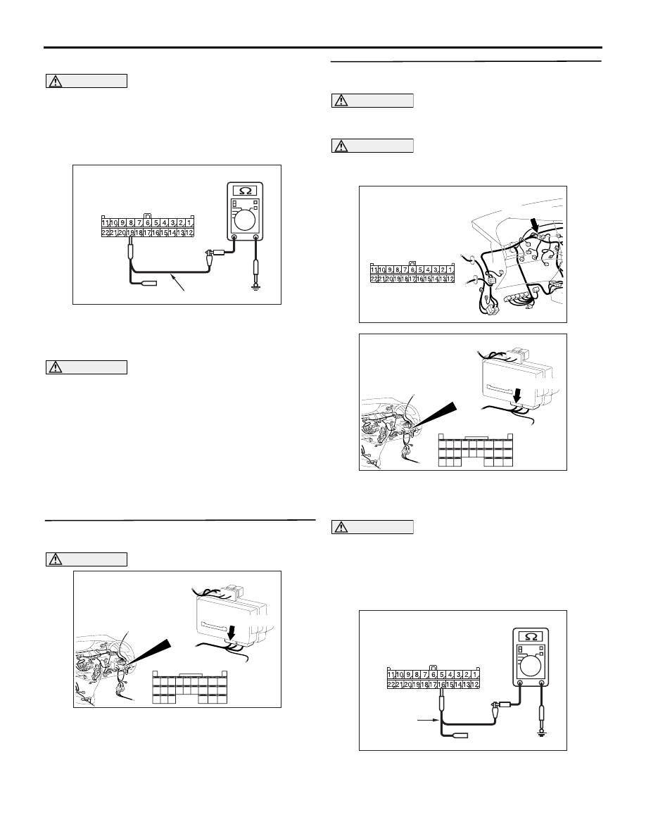
harness side.
CAUTION
When measuring the resistance, disconnect the
negative battery terminal. For details refer to
(2) Ensure that the negative battery terminal is
disconnected.
(3) Resistance between C-09 joint connector (CAN2)
terminal No.19 and body earth
OK: 1 k
Ω or more
CAUTION
Strictly observe the specified wiring harness
repair procedure. For details refer to
Q: Is the check result normal?
YES :
<less than 1.0 V> Follow diagnostic item 19
"Diagnose CAN bus lines thoroughly." Refer
to
NO :
<1.0 V or more> Repair the wiring harness
between the joint connector (CAN2) and the
A/C-ECU connector.
STEP 10. Connector check: C-221 ETACS-ECU
connector
CAUTION
The strand end of the twist wire should be within
10 cm from the connector. For details refer to
Q: Is the check result normal?
YES :
Go to Step 11.
NO :
Repair the defective connector.
STEP 11. Resistance measurement at C-09 joint
connector (CAN2).
CAUTION
A digital multimeter should be used. For details
refer to
.
CAUTION
The test wiring harness should be used. For
details refer to
(1) Disconnect the joint connector (CAN2) and the
ETACS-ECU connector, and measure at the
wiring harness side.
CAUTION
When measuring the resistance, disconnect the
negative battery terminal. For details refer to
(2) Ensure that the negative battery terminal is
disconnected.
(3) Resistance between C-09 joint connector (CAN2)
AC209364LF
Harness side: C-09
Test harness
AC310620
Connector: C-221
Junction block
(Rear view)
<RHD>
AC
51
52
53
54
55
56
57
58
59
60
61
62
63
64
65
66
67
68
69
70
71
72
73
74
Harness side
C-221(GR)
AC310628AY
Connector: C-09 <RHD>
C-09 (GR)
Harness side
AC310620
Connector: C-221
Junction block
(Rear view)
<RHD>
AC
51
52
53
54
55
56
57
58
59
60
61
62
63
64
65
66
67
68
69
70
71
72
73
74
Harness side
C-221(GR)
AC209364MF
Harness side: C-09
Test
harness