Mitsubishi Grandis. Manual - part 333
REAR BLOWER MOTOR AND REAR POWER TRANSISTOR
HEATER, AIR CONDITIONER AND VENTILATION
55-217
REAR BLOWER MOTOR AND REAR POWER TRANSISTOR
REMOVAL AND INSTALLATION
M1554015500027
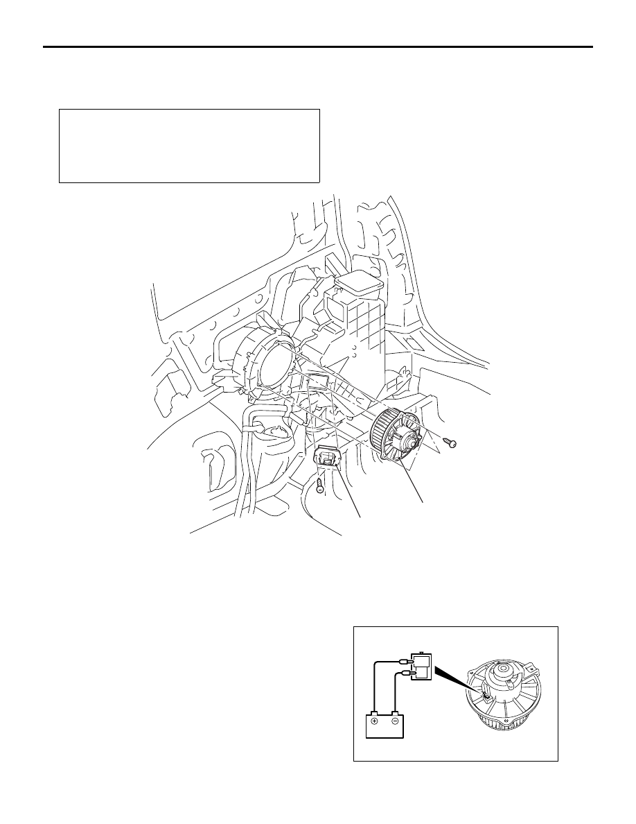
INSPECTION
M1554011900045
REAR BLOWER MOTOR INSPECTION
<VEHICLES WITH REAR HEATER, REAR
COOLER OR DUAL AUTOMATIC A/C>
Pre-removal and Post-installation Operation
• Third seat assembly Removal and Installation (Refer to
GROUP 52A, Third Seat Assembly
.)
• Quarter trim lower, quarter trim upper Removal and
Installation (Refer to GROUP 52A, Interior Trim
AC302929
1
2
AC
Rear power transistor removal
step
1.
Rear power transistor <Vehicles
with rear heater, rear cooler or dual
automatic A/C>
Rear blower motor removal
steps
•
Rear floor duct A <Vehicles with
rear heater or rear A/C> (Refer to
2.
Rear blower motor <Vehicles with
rear heater, rear cooler or dual
automatic A/C>
AC303108
2
1