Mitsubishi Grandis. Manual - part 331


  Index      Mitsubishi     Mitsubishi Grandis - service repair manual


Search            


Content   ..  329  330  331  332   ..


Mitsubishi Grandis. Manual - part 331


MODE SELECTION DAMPER CONTROL MOTOR, AIR MIXING DAMPER CONTROL MOTOR, OUTSIDE/INSIDE 

HEATER, AIR CONDITIONER AND VENTILATION

55-209

MOTOR CHECK

Potentiometer check
When the resistance value between connector 
terminals 3 and 5 is measured while checking the 
motor, check that the resistance value changes 
gradually within the standard value.

Standard value: 1.7 (MAX HOT) 

 5.0 (MAX 

COOL) k

CHECK THE OUTSIDE/INSIDE AIR 
SELECTION DAMPER MOTOR

CAUTION

Stop energizing when the lever is set to the 
operation stopping position.

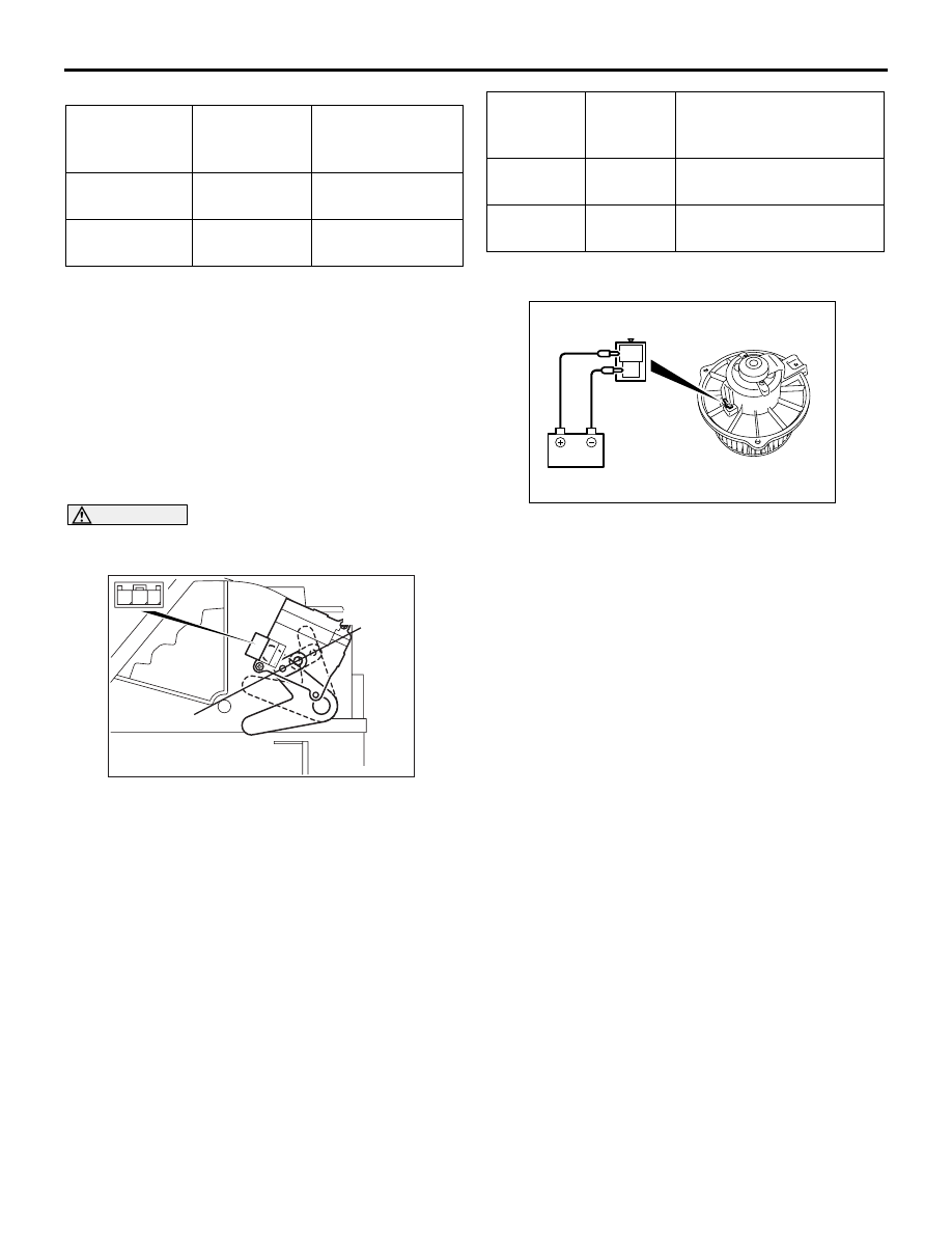
FRONT BLOWER MOTOR CHECK

Check that the motor turns when applying battery 
power between the connector terminals. Also check 
to see that there is no abnormal sound emitted from 
the motor at this time.

Battery 
connection 
(+) terminal

Battery 
connection 
(-) terminal

Lever operation

2

1

Rotate to the HOT 
side.

1

2

Rotate to the 
COOL side.

AC311449AB

1 2 3

Outside air

Inside air

Connectio
n (+) 
terminal

Connecti
on (-) 
terminal

Lever operation

1

2

The rotation stops at the 
fresh air position

1

3

The rotation stops at the 
air recirculation position

AC303108

2

1

PHOTO SENSOR AND INTERIOR TEMPERATURE SENSOR

HEATER, AIR CONDITIONER AND VENTILATION

55-210

PHOTO SENSOR AND INTERIOR TEMPERATURE SENSOR

REMOVAL AND INSTALLATION

M1554015100029

REMOVAL SERVICE POINTS
<<A>> PHOTO SENSOR REMOVAL

Cut the connector behind the combination meter 
away and tie it with string so that the photo sensor 
can be drawn out from the instrument panel easily.

AC310253

3

1

2

AB

Inside temperature sensor 
removal steps

Cowl side trim (Refer to GROUP 
52A, Interior Trim 

P.52A-10

.)

Selector lever, selector lever panel 
and instrument lower panel (Refer 
to GROUP 52A, Instrument Panel 

P.52A-2

.)

1.

Interior temperature sensor

2.

Aspirator hose
Photo sensor removal steps

Combination meter bezel, 
combination meter (Refer to 
GROUP 54A, Combination meter 

P.54A-84

.)

Door opening trim, front pillar trim 
(Refer to GROUP 52A,Interior Trim 

P.52A-10

.)

Defroster garnish (Refer to GROUP 
52A, Instrument Panel 

P.52A-2

.)

<<A>>

3.

Photo sensor

AC311447AB

Photo sensor

String

AMBIENT TEMPERATURE SENSOR

HEATER, AIR CONDITIONER AND VENTILATION

55-211

INSPECTION

M1552014301395

INTERIOR TEMPERATURE SENSOR 
CHECK

Check to see that the resistance shown in the graph 
is almost satisfied when measuring the resistance 
between the terminals under two or more different 
temperature conditions.

PHOTO SENSOR CHECK

Check that the display voltage changes between in 
direct sunlight and in doors when checking the 
MUT-III service data item No.06.

AMBIENT TEMPERATURE SENSOR

REMOVAL AND INSTALLATION

M1554003400131

INSPECTION

M1552014301403

Check to see that the resistance shown in the graph 
is almost satisfied when measuring the resistance 
between the sensor terminals under two or more 
different temperature conditions.

AC103488

20

15

10

5

0

-10 0

20

40

60

80

AB

Resis
tance
(k

Ω)

Temperature (˚C)

Removal steps

Front bumper (GROUP 51, Front 
Bumper 

P.51-3

.)

1.

Ambient temperature sensor

AC302862 AB

1

AC209192AB

10

8

6

4

2

0

10

20

30

40

-10

0

RESISTANCE

(k

Ω)

TEMPERATURE (˚C)

HEAT SWITCH

HEATER, AIR CONDITIONER AND VENTILATION

55-212

HEAT SWITCH

REMOVAL AND INSTALLATION <REAR 
HEATER OR REAR A/C VEHICLES>

M1554017000028

INSPECTION

M1554011900034

PTC HEATER SWITCH CONTINUITY 
CHECK

AC311594AB

1

3

2

 Removal steps

1.

Combination meter bezel (GROUP 
52A, Instrument Panel 

P.52A-2

.)

2.

Heat switch holder

3.

Heat switch (PTC heater switch)

Switch 
position

Tester connection  Specified 

condition

OFF

− 2

Open circuit

ON

Less than 2 ohms

AC303103

1 2 3

4 5 6


Content   ..  329  330  331  332   ..