Mitsubishi Grandis. Manual - part 332
REAR A/C SWITCH
HEATER, AIR CONDITIONER AND VENTILATION
55-213
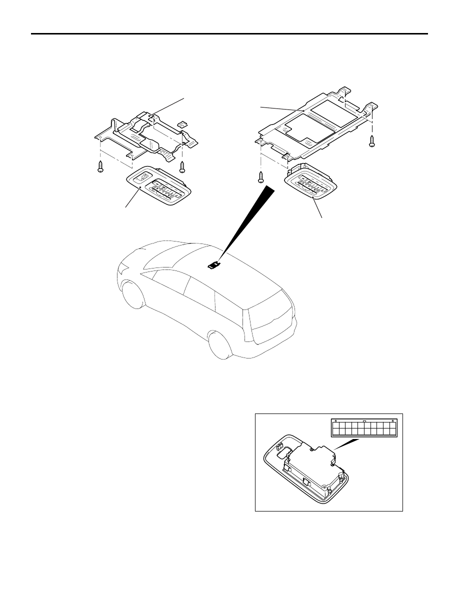
REAR A/C SWITCH
REMOVAL AND INSTALLATION
M1554017200022
INSPECTION
M1552014301414
REAR HEATER CONTROLLER
CONTINUITY CHECK
AC303126
2
1
1
2
AB
<Vehicles with sunroof>
<Vehicles without sunroof>
Removal steps
1.
Rear heater controller (Refer to
GROUP 52A, Headlining
•
Headlining (Refer to GROUP 52A,
Headlining
2.
Rear heater controller bracket
AC303225
1 2 3 4 5 6 7 8 9 10
11 12 13 14 15 16 17 18 19 20