Mitsubishi Grandis. Manual - part 115


  Index      Mitsubishi     Mitsubishi Grandis - service repair manual


Search            


Content   ..  113  114  115  116   ..


Mitsubishi Grandis. Manual - part 115


INPUT SIGNAL PROCEDURES

SMART WIRING SYSTEM (SWS) NOT USING SWS MONITOR

54B-457

Step 10. Retest the system.

Check that each switch signal is received by 
operating the sunroof switch.

Q: Is the check result normal?

YES : 

The trouble can be an intermittent 

malfunction (Refer to GROUP 00 

− How to 

Cope with Intermittent Malfunction 

P.00-5

).

NO : 

Replace the sunroof motor assembly.

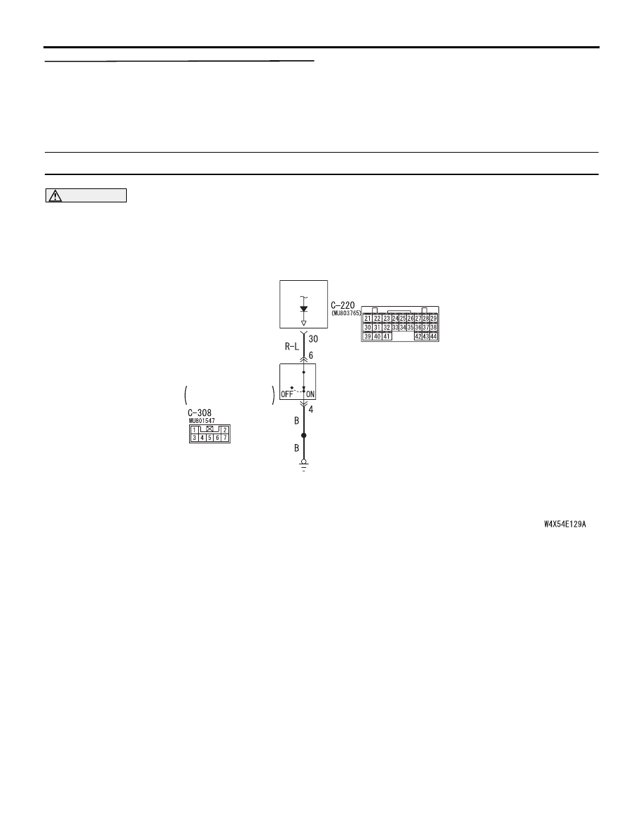
Inspection Procedure Q-11: The key reminder switch signal is not received.

CAUTION

Whenever the ECU is replaced, ensure that the 
input signal circuit is normal.

COMMENTS ON TROUBLE SYMPTOM

Input signal from the key reminder switch is used to 
operate the functions below. If the signal is abnormal, 
these functions will not work normally.

• Key reminder function

• Keyless entry system

• Ignition key cylinder illumination lamp

• Interior lamps

POSSIBLE CAUSES

• Malfunction of the key reminder switch

• Malfunction of the ETACS-ECU

• Damaged harness wires and connectors

ETACS-
ECU

KEY
REMINDER
SWITCH

Wire colour code
B : Black     LG : Light green     G : Green     L : Blue     W : White     Y : Yellow     SB : Sky blue
BR : Brown     O : Orange     GR : Gray     R : Red     P : Pink     V : Violet

WHEN REMOVING
KEY: ON

Key Reminder Switch Input Circuit

INPUT SIGNAL PROCEDURES

SMART WIRING SYSTEM (SWS) NOT USING SWS MONITOR

54B-458

DIAGNOSTIC PROCEDURE

Step 1. Connector check: C-308 key reminder 
switch connector

Q: Is the check result normal?

YES : 

Go to Step 2.

NO : 

Repair the defective connector.

Step 2. Check the key reminder switch.
Refer to GROUP 54A 

− Ignition switch 

P.54A-31

.

Q: Is the check result normal?

YES : 

Go to Step 3.

NO : 

Replace the key reminder switch.

Step 3. Resistance measurement at the C-308 key 
reminder switch connector.

(1) Disconnect the connector, and measure at the 

wiring harness side.

(2) Resistance between C-308 key reminder switch 

connector terminal No.4 and body earth

OK: 2 

 or less

Q: Is the check result normal?

YES : 

Go to Step 5.

NO : 

Go to Step 4.

AC312039

2
7 6

1
3

5 4

Connector: C-308 <LHD>

AB

Harness side

AC312049

2
7 6

1
3

5 4

Connector: C-308 <RHD>

AB

Harness side

AC312039

2
7 6

1
3

5 4

Connector: C-308 <LHD>

AB

Harness side

AC312049

2
7 6

1
3

5 4

Connector: C-308 <RHD>

AB

Harness side

AC312730AB

Connector C-308
(Harness side)

2
7 6

1
3

5 4

INPUT SIGNAL PROCEDURES

SMART WIRING SYSTEM (SWS) NOT USING SWS MONITOR

54B-459

Step 4. Check the wiring harness between C-308 
key reminder switch connector terminal No.4 and 
the body earth.

• Check the earth wires for open circuit.

Q: Is the check result normal?

YES : 

The trouble can be an intermittent 

malfunction (Refer to GROUP 00 

− How to 

Cope with Intermittent Malfunction 

P.00-5

).

NO : 

Repair the wiring harness.

Step 5. Connector check: C-220 ETACS-ECU 
connector

Q: Is the check result normal?

YES : 

Go to Step 6.

NO : 

Repair the defective connector.

AC312039

2
7 6

1
3

5 4

Connector: C-308 <LHD>

AB

Harness side

AC312049

2
7 6

1
3

5 4

Connector: C-308 <RHD>

AB

Harness side

AC312037

Connector: C-220

Junction block (Rear view)

AC

<LHD>

Harness side

AC312047

Connector: C-220

Junction block (Rear view)

AC

<RHD>

Harness side

INPUT SIGNAL PROCEDURES

SMART WIRING SYSTEM (SWS) NOT USING SWS MONITOR

54B-460

Step 6. Check the wiring harness between C-308 
key reminder switch connector terminal No.6 and 
C-220 ETACS-ECU connector terminal No.30.

• Check the input line for open circuit.

Q: Is the check result normal?

YES : 

Go to Step 7.

NO : 

Repair the wiring harness.

Step 7. Retest the system.
Check that the key reminder switch signal is received 
normally.

Q: Is the check result normal?

YES : 

The trouble can be an intermittent 

malfunction (Refer to GROUP 00 

− How to 

Cope with Intermittent Malfunction 

P.00-5

).

NO : 

Replace the ETACS-ECU.

AC312037

Connector: C-220

Junction block (Rear view)

AC

<LHD>

Harness side

AC312047

Connector: C-220

Junction block (Rear view)

AC

<RHD>

Harness side

AC312039

2
7 6

1
3

5 4

Connector: C-308 <LHD>

AB

Harness side

AC312049

2
7 6

1
3

5 4

Connector: C-308 <RHD>

AB

Harness side


Content   ..  113  114  115  116   ..