Mitsubishi Grandis. Manual - part 1039


  Index      Mitsubishi     Mitsubishi Grandis - service repair manual


Search            


Content   ..  1037  1038  1039  1040   ..


Mitsubishi Grandis. Manual - part 1039


SRS MAINTENANCE

SUPPLEMENTAL RESTRAINT SYSTEM (SRS)

52B-208

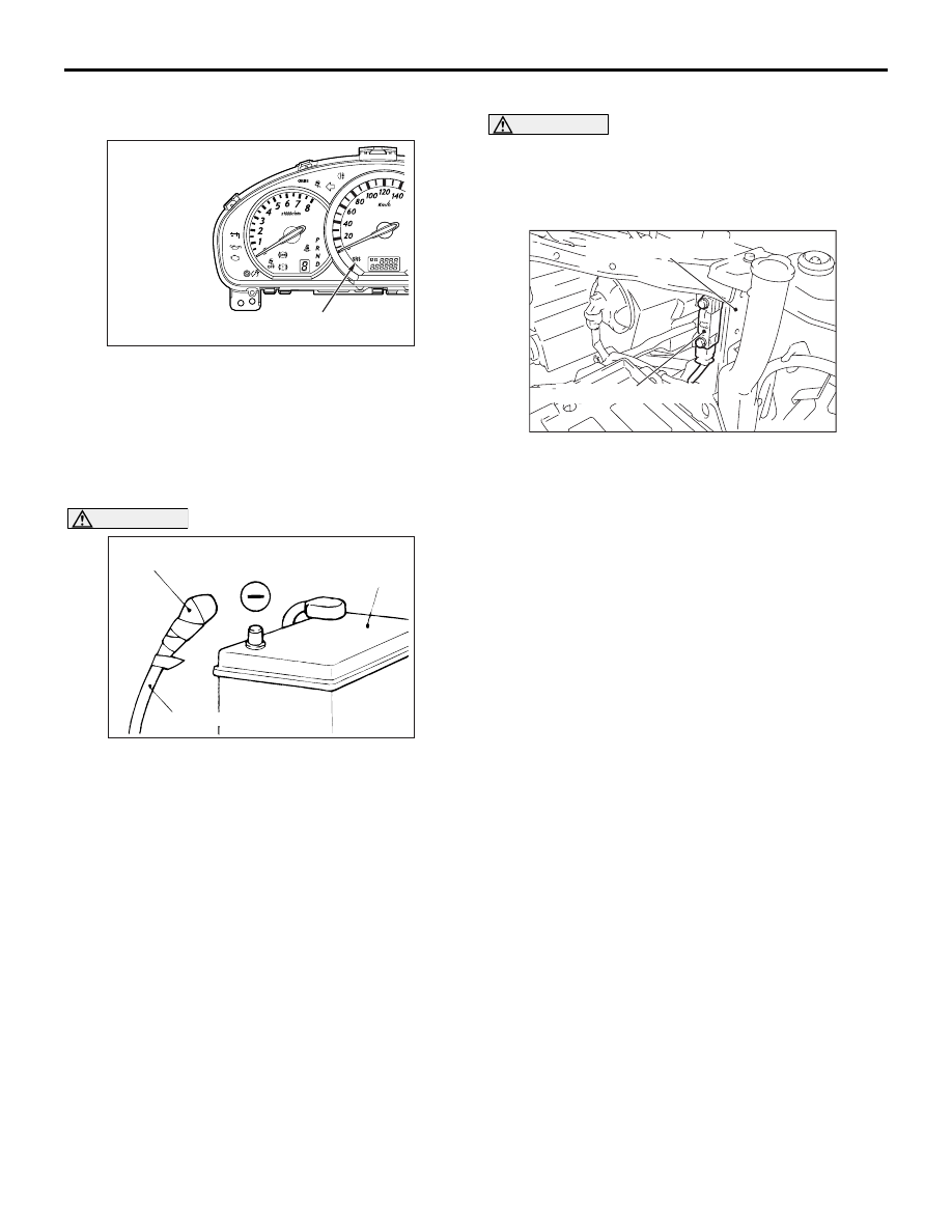
SRS WARNING LAMP CHECK

Turn the ignition key to the "ON" position. Does the 
SRS warning lamp illuminate for about 7 seconds, 
turn off and then remain extinguished for at least 5 
seconds? If yes, SRS system is functioning properly. 
If no, consult page 

P.52B-13

.

SRS COMPONENT VISUAL CHECK

DANGER

Wait at least 60 seconds after disconnecting 
the battery cable before doing any further 
work (Refer to 

P.52B-7

).

Turn the ignition key to the "LOCK" position, 
disconnect the negative battery cable and tape the 
terminal.

FRONT IMPACT SENSOR

WARNING

The SRS may not activate if the impact 
sensors are not installed properly, which 
could result in serious injury or death to the 
vehicle's driver or front passenger.

1. Check the front side member and front impact 

sensor for deformation or rust.

2. Check the front impact sensor for dents, cracks, 

deformation or rust.

3. Check the sensor harnesses for binding, the 

connectors for damage, and the terminals for 
deformation.

NOTE: The figures show front impact sensors (LH). 
The side impact sensors (RH) are symmetrical with 
the side impact sensors (LH).

AC312486

SRS warning lamp

AB

AC300580AB

Insulating tape

Battery

Battery cable

AC311405

Radiator support panel

AB

Front impact sensor (LH)

SRS MAINTENANCE

SUPPLEMENTAL RESTRAINT SYSTEM (SRS)

52B-209

SRS CONTROL UNIT (SRS-ECU) 

WARNING

The SRS may not activate if the SRS-ECU is 
not installed properly, which could result in 
serious injury or death to the vehicle's driver 
or front passenger.

1. Check the SRS-ECU case and brackets for dents, 

cracks, deformation or rust.

2. Check the connector for damage, and check the 

terminals for deformation or rust.
Replace the SRS-ECU if it fails the visual checks 
above (Refer to 

P.52B-223

).

AIR BAG MODULES, STEERING WHEEL 
AND CLOCK SPRING 

WARNING

The removed air bag module should be 
stored in a clean, dry place with the pad 
cover face up.

1. Remove the air bag module, steering wheel and 

clock spring (Refer to 

P.52B-225

).

2. Check the pad cover for dents, cracks or 

deformation.

3. Check the connector for damage and deformed 

terminals, and check the harness for binding.

4. Check the air bag inflator case for dents, cracks or 

deformation.

5. Check the harness (built into the steering wheel) 

and connectors for damage, and check the 
terminals for deformation.

6. Check the clock spring connectors and protective 

tube for damage, and terminals for deformities.

7. Visually check the case for damage.

AC300929

AC311438

AC312488AB

SRS-ECU

Shift lever assembly

AC312188AB

Inflator case

Connector

<Driver's side>

<Passenger's (front) side>

Inflator case

Connector

AC306766AD

Case

Protective tubes

SRS MAINTENANCE

SUPPLEMENTAL RESTRAINT SYSTEM (SRS)

52B-210

WARNING

If the clock spring's mating mark is not 
properly aligned, the steering wheel may not 
be completely rotational during a turn, or the 
flat cable within the clock spring may be 
severed, obstructing normal operation of the 
SRS and possibly leading to serious injury to 
the vehicle's driver or front passenger.

8. Align the mating marks of the clock spring and, 

after turning the vehicle's front wheels to 
straight-ahead position, install the clock spring to 
the column switch.
Mating Marks Alignment;
Turn the clock spring clockwise fully. Then turn it 
back approximately 3 3/4 turns anticlockwise to 
align the mating marks.

9. Turn the front wheels to the straight-ahead 

position. Then install the clock spring to the 
column switch.

CAUTION

Ensure that the steering wheel sensor’s mating 
marks are properly aligned. If not, the steering 
wheel sensor could be damaged.
10.On vehicles with ASC, align the mating marks of 

the steering wheel sensor as follows.
<Mating Mark Alignment>

(1) Removal the steering wheel sensor (Refer to 

GROUP 35C, Steering Wheel Sensor 

P.35C-168

).

(2) Turn the steering wheel sensor clockwise fully. 

Then turn it back approximately 2-3/4 turns 
counterclockwise to align the mating marks.

(3) Align the mating marks on the clock spring and 

the steering wheel sensor, and install the 
steering wheel sensor to the column switch 
assembly.

(4) Connect the steering wheel sensor connector.

11.Install the steering column covers, steering wheel 

and air bag module (Refer to 

P.52B-225

).

12.Check the steering wheel for noise, binding or 

difficult operation.

DANGER

The SRS may not activate if any of the above 
components is not installed properly, which 
could result in serious injury or death to the 
vehicle's driver or front passenger.

13.Check the steering wheel for excessive free play.
14.Replace any visually inspected part if it fails that 

inspection (Refer to 

P.52B-230

).

FRONT SEATBACK ASSEMBLY WITH 
SIDE-AIRBAG MODULE

1. Check the side-airbag module deployment section 

in the seat for dents and deformation.

2. Check the harness for binds, the connector for 

damage and the terminals for deformation.

SEAT BELT WITH PRE-TENSIONER

1. Check the seat belt pre-tensioner for dents or 

deformation.

2. Check that the seat belt pre-tensioner is installed 

correctly to the vehicle body.

AC306756AC

Mating marks

AC308437AC

Steering wheel
sensor

Mating mark

AC303516

AD

Side-airbag module
deployment section

SRS MAINTENANCE

SUPPLEMENTAL RESTRAINT SYSTEM (SRS)

52B-211

SIDE IMPACT SENSOR

WARNING

The SRS may not activate if the impact 
sensors are not installed properly, which 
could result in serious injury or death to the 
vehicle's driver or front passenger.

1. Check the centre pillar and quarter inner panel for 

deformation or rust.

2. Check the side impact sensors for dents, cracks, 

deformation and rust.

3. Check the connector for damage and the 

terminals for deformation.

NOTE: The figures show side impact sensors (LH). 
The side impact sensors (RH) are symmetrical with 
the side impact sensors (LH).

CURTAIN AIR BAG MODULE

1. Check that the curtain air bag deployment part of 

the headlining is normal.

2. Check the inflator surface for cracks, dents or 

deformations.

3. Check the air bag for breakage.
4. Check the connector for damage, the terminal for 

deformation and the harness for binding.

SEAT SLIDE SENSOR

1. Check that there is no connector damage, bent 

terminals or harness crimping.

2. Check the installation of the seat slide sensor.

PASSENGER’S AIR BAG CUT OFF 
SWITCH

1. Check the passenger’s air bag cut off switch for 

dents or deformation.

2. Check the installation of the passenger’s air bag 

cut off switch.

AC302574

AC311614

AC312491

Centre pillar

Second
seat belt

Side impact 
sensor (rear)

Side impact 
sensor (front)

<Front>

<Rear>

AB

AC302258AC

Inflator

Curtain air bag module
deployment section

AC311621

AC312492

AC311625

Seat slide 
adjuster

Seat slide 
sensor

Front seat
(Driver's side)

AB

AC312598AB

Passenger's air bag
cut off switch

Glove box


Content   ..  1037  1038  1039  1040   ..