Mitsubishi Grandis. Manual - part 1037


  Index      Mitsubishi     Mitsubishi Grandis - service repair manual


Search            


Content   ..  1035  1036  1037  1038   ..


Mitsubishi Grandis. Manual - part 1037


TROUBLESHOOTING

SUPPLEMENTAL RESTRAINT SYSTEM (SRS)

52B-200

SYMPTOM PROCEDURES

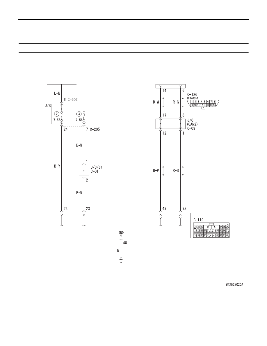
Inspection Procedure 1: Communication between Scan Tool and the SRS-ECU is not possible.

COMMENTS ON TROUBLE SYMPTOM

If the MUT-III can not communicate with the SRS 
system, the CAN bus lines may be defective. If the 
SRS system does not work, the SRS-ECU or its 
power supply circuit may be defective. 

PROBABLE CAUSES

• Damaged wiring harness or connector

• Malfunction of the SRS-ECU

Wire colour code
B : Black     LG : Light green     G : Green     L : Blue     W : White     Y : Yellow     SB : Sky blue
BR : Brown     O : Orange     GR : Gray     R : Red     P : Pink     V : Violet

IGNITION
SWITCH (IG1)

SRS-ECU

DIAGNOSIS
CONNECTOR

FRONT SIDE

Data Link Connector Circuit

TROUBLESHOOTING

SUPPLEMENTAL RESTRAINT SYSTEM (SRS)

52B-201

DIAGNOSIS PROCEDURE

STEP 1. MUT-III CAN bus diagnostics
Use the MUT-III to diagnose the CAN bus lines.

Q: Is the check result normal?

YES : 

Check and repair the power supply circuit 

system (Refer to 

P.52B-201

). 

NO : 

Repair the CAN bus lines (Refer to GROUP 
54D, Diagnosis-

P.54D-16

). 

INSPECTION PROCEDURE 2: Power Supply Circuit System

Wire colour code
B : Black     LG : Light green     G : Green     L : Blue     W : White     Y : Yellow     SB : Sky blue
BR : Brown     O : Orange     GR : Gray     R : Red     P : Pink     V : Violet

IGNITION
SWITCH (IG1)

SRS-ECU

IG1 Power Supply Circuit <LH drive vehicles>

TROUBLESHOOTING

SUPPLEMENTAL RESTRAINT SYSTEM (SRS)

52B-202

OPERATION

• The SRS-ECU is energized by the ignition switch 

(IG1) through multi-purpose fuse 2 and the 
SRS-ECU terminal 24 and multi-purpose fuse 3 
and the SRS-ECU terminal 23.

• If the power supply to the SRS-ECU has failed, 

MUT-III will not be able to communicate with it.

PROBABLE CAUSES

• Damaged wiring harness or connector

• Defective battery

• Charging system failed

• Malfunction of the SRS-ECU

Wire colour code
B : Black     LG : Light green     G : Green     L : Blue     W : White     Y : Yellow     SB : Sky blue
BR : Brown     O : Orange     GR : Gray     R : Red     P : Pink     V : Violet

IGNITION
SWITCH (IG1)

SRS-ECU

IG1 Power Supply Circuit <RH drive vehicles>

TROUBLESHOOTING

SUPPLEMENTAL RESTRAINT SYSTEM (SRS)

52B-203

DIAGNOSIS PROCEDURE

STEP 1. Resistance measurement at SRS-ECU 
connector C-119.

(1) Disconnect the connector C-119.

CAUTION

Do not insert a test probe into the terminal from 
its front side directly, as the connector contact 
pressure may be weakened.
(2) Check for continuity between C-119 harness side 

connector terminals 40 and body earth.

OK: Less than 2 

Q: Is the check results normal?

YES : 

Then go to Step 2 .

NO : 

Repair the wiring harness between 
SRS-ECU connector C-119 terminals 40 
and the body earth. Then go to Step 3 .

AC311438 AD

C-119 (Y)

Connector: C-119

Harness side
(front view)

AC308208

42

31

38

27

21

41

28

39

22

30

25

47

36

33

44

34

45

37

48

26

29

23

40

32

43

35

46

24

B

A

C-119 Harness side
connector (rear view)

AD


Content   ..  1035  1036  1037  1038   ..