Mitsubishi Grandis. Manual - part 88


  Index      Mitsubishi     Mitsubishi Grandis - service repair manual


Search            


Content   ..  86  87  88  89   ..


Mitsubishi Grandis. Manual - part 88


SYMPTOM PROCEDURES

SMART WIRING SYSTEM (SWS) NOT USING SWS MONITOR

54B-349

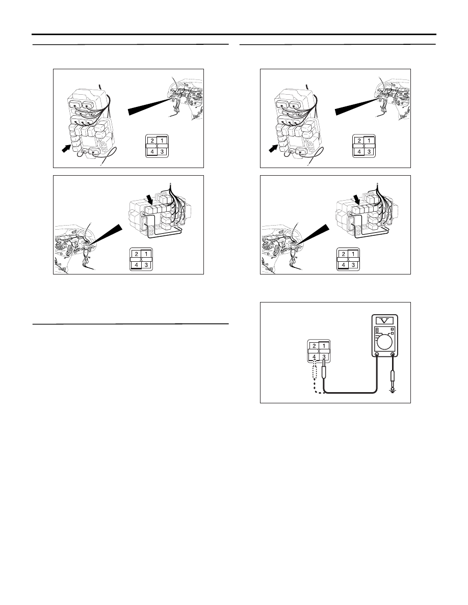
Step 7. Connector check: C-213 rear fog lamp 
relay connector

Q: Is the check result normal?

YES : 

Go to Step 8.

NO : 

Repair the defective connector.

Step 8. Check the rear fog lamp relay.

Refer to GROUP 54A 

− Rear fog lamp 

P.54A-94

.

Q: Is the check result normal?

YES : 

Go to Step 9.

NO : 

Replace the rear fog lamp relay.

Step 9. Voltage measurement at the C-213 rear 
fog lamp relay connector.

(1) Remove the rear fog lamp relay, and measure at 

the relay box side.

(2) Check the voltage between the rear fog lamp 

relay connector and body earth.

• Voltage between C-213 rear fog lamp relay 

connector terminal No.3 and body earth

• Voltage between C-213 rear fog lamp relay 

connector terminal No.4 and body earth

OK: System voltage

Q: Is the check result normal?

YES : 

Go to Step 11.

NO : 

Go to Step 10.

AC310623

Connector: C-213 <LHD>

AP

Junction block side

Junction block (Front view)

AC310618

Connector: C-213 <RHD>

AN

Junction block side

Junction block (Front view)

AC310623

Connector: C-213 <LHD>

AP

Junction block side

Junction block (Front view)

AC310618

Connector: C-213 <RHD>

AN

Junction block side

Junction block (Front view)

AC310507

AC310507BW

Connector C-213 
(Relay box side)

SYMPTOM PROCEDURES

SMART WIRING SYSTEM (SWS) NOT USING SWS MONITOR

54B-350

Step 10. Check the wiring harness between C-213 
rear fog lamp relay connector (terminal Nos.3 
and 4) and the Fusible link (30).

NOTE: 

AC310623

Connector: C-213 <LHD>

AP

Junction block side

Junction block (Front view)

AC310618

Connector: C-213 <RHD>

AN

Junction block side

Junction block (Front view)

SYMPTOM PROCEDURES

SMART WIRING SYSTEM (SWS) NOT USING SWS MONITOR

54B-351

Prior to the wiring harness inspection, check 
intermediate connector C-125 and junction block 
connectors C-204 and C-205, and repair if 
necessary.

• Check the power supply line for open circuit.

Q: Is the check result normal?

YES : 

The trouble can be an intermittent 

malfunction (Refer to GROUP 00 

− How to 

Cope with Intermittent Malfunction 

P.00-5

).

NO : 

Repair the wiring harness.

AC310613

AD

Connector: C-125 <LHD>

AC310628AB

Connector: C-125 <RHD>

AC310624

Connectors: C-204, C-205 <LHD>

AQ

Junction block side

Junction block (Front view)

C-204 (B)

C-205

Harness side

C-204

C-205

AC310619

Connectors: C-204, C-205 <RHD>

AQ

Junction block side

Junction block (Front view)

C-204 (B)

C-205

Harness side

C-204

C-205

SYMPTOM PROCEDURES

SMART WIRING SYSTEM (SWS) NOT USING SWS MONITOR

54B-352

Step 11. Check the wiring harness from G-23 rear 
fog lamp connector <LH drive vehicles> or G-11 
rear fog lamp connector <RH drive vehicles> 
terminal No.2 to C-213 rear fog lamp relay 
connector terminal No.1.

NOTE: 

Prior to the wiring harness inspection, check 

AC310222

Connector: G-11

AE

G-11 (GR)

Harness side

AC310220

Connector: G-23

AE

G-23 (GR)

Harness side

AC310623

Connector: C-213 <LHD>

AP

Junction block side

Junction block (Front view)

AC310618

Connector: C-213 <RHD>

AN

Junction block side

Junction block (Front view)

AC310631AQ

Connector: C-15 <RHD>

AC310615

AN

<LHD>

Connector: C-16

AC310220

Connector: G-21 <LHD>

AC

AC310623

Connector: C-201 <LHD>

AR

Harness side

Junction block (Front view)

AC310618

Connector: C-201 <RHD>

AP

Harness side

Junction block (Front view)


Content   ..  86  87  88  89   ..