Mitsubishi Grandis. Manual - part 87


  Index      Mitsubishi     Mitsubishi Grandis - service repair manual


Search            


Content   ..  85  86  87  88   ..


Mitsubishi Grandis. Manual - part 87


SYMPTOM PROCEDURES

SMART WIRING SYSTEM (SWS) NOT USING SWS MONITOR

54B-345

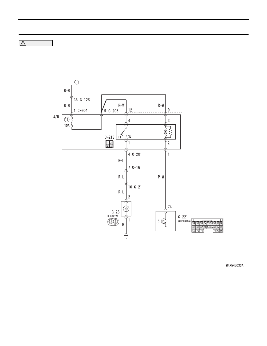
Inspection Procedure O-2: The rear fog lamps do not illuminate normally.

CAUTION

Whenever the ECU is replaced, ensure that the 
input and output signal circuits are normal.

Wire colour code
B : Black     LG : Light green     G : Green     L : Blue     W : White     Y : Yellow     SB : Sky blue
BR : Brown     O : Orange     GR : Gray     R : Red     P : Pink     V : Violet   

ETACS-ECU

FUSIBLE
LINK

REAR FOG
LAMP

REAR 
FOG 
LAMP 
RELAY

30

Rear Fog Lamp Circuit <LHD>

SYMPTOM PROCEDURES

SMART WIRING SYSTEM (SWS) NOT USING SWS MONITOR

54B-346

POSSIBLE CAUSES

• Malfunction of the column switch

• Malfunction of the fog lamp switch

• Malfunction of the ETACS-ECU

• Damaged harness wires and connectors

DIAGNOSTIC PROCEDURE

Step 1. Check that the tail/stop lamps and 
headlamps operate.
Check that the tail/stop lamps and headlamps 
illuminate normally.

Q: Is the check result normal?

YES : 

Go to Step 2.

NO : 

Check the tail/stop lamps and the 
headlamps (Refer to trouble symptom chart 

P.54B-74

).

Wire colour code
B : Black     LG : Light green     G : Green     L : Blue     W : White     Y : Yellow     SB : Sky blue
BR : Brown     O : Orange     GR : Gray     R : Red     P : Pink     V : Violet   

ETACS-ECU

FUSIBLE
LINK

REAR FOG
LAMP

REAR 
FOG 
LAMP 
RELAY

30

Rear Fog Lamp Circuit <RHD>

SYMPTOM PROCEDURES

SMART WIRING SYSTEM (SWS) NOT USING SWS MONITOR

54B-347

Step 2. Pulse check
Check the input signals below, which are related to 
the rear fog lamps.

OK: The MUT-III sounds or the voltmeter 
needle fluctuates.

Q: Is the check result normal?

All the signals are received normally. : 

Go to Step 

3.

The ignition switch (IG1) signal is not received. : 

Refer to inspection procedure Q-2 "The 
ignition switch (IG1) signal is not received 

P.54B-420

."

The tail lamp switch signal is not received. : 

Refer 

to inspection procedure Q-6 "The column 
switch (lighting and turn-signal lamp and 
headlamp washer switch) signal is not 
received 

P.54B-438

."

The headlamp switch signal is not received. : 

Refer to inspection procedure Q-6 "The 
column switch (lighting and turn-signal lamp 
and headlamp washer switch) signal is not 
received 

P.54B-438

."

The rear fog lamp switch signal is not received. : 

Refer to inspection procedure Q-13 "The 
rear fog lamp switch signal is not received 

P.54B-465

."

Step 3. Connector check: G-23 rear fog lamp 
connector <LH drive vehicles> or G-11 rear fog 
lamp connector <RH drive vehicles>

Q: Is the check result normal?

YES : 

Go to Step 4.

NO : 

Repair the defective connector.

Step 4. Check the bulbs of the rear fog lamps.
Check the bulb(s) of the defective lamp.

Q: Is the check result normal?

YES : 

Go to Step 5.

NO : 

Replace the bulb(s) of the defective lamp.

System switch

Check condition

Ignition switch (IG1)

When turned from ACC 
to ON

Tail lamp switch

When the lighting switch 
is turned to the TAIL 
position

Headlamp switch

When the lighting switch 
is turned to the 
HEADLAMP position

Rear fog lamp switch

When the rear fog lamp 
switch is turned from off 
to on

AC310222

Connector: G-11

AE

G-11 (GR)

Harness side

AC310220

Connector: G-23

AE

G-23 (GR)

Harness side

SYMPTOM PROCEDURES

SMART WIRING SYSTEM (SWS) NOT USING SWS MONITOR

54B-348

Step 5. Resistance measurement at the G-23 rear 
fog lamp connector <LH drive vehicles> or G-11 
rear fog lamp connector <RH drive vehicles>.

(1) Disconnect the connector, and measure at the 

wiring harness side.

(2) Check the resistance between the lamp 

connector and body earth.

• Resistance between G-23 rear fog lamp relay 

connector <LH drive vehicles> or G-11 rear 
fog lamp relay connector <RH drive vehicles> 
connector terminal No.1 and body earth

OK: 2 

 or less

Q: Is the check result normal?

YES : 

Go to Step 7.

NO : 

Go to Step 6.

Step 6. Check the wiring harness from G-23 rear 
fog lamp connector <LH drive vehicles> or G-11 
rear fog lamp connector <RH drive vehicles> 
terminal No.1 to body earth.

• Check the earth wires for open circuit.

Q: Is the check result normal?

YES : 

The trouble can be an intermittent 

malfunction (Refer to GROUP 00 

− How to 

Cope with Intermittent Malfunction 

P.00-5

).

NO : 

Repair the wiring harness.

AC310222

Connector: G-11

AE

G-11 (GR)

Harness side

AC310220

Connector: G-23

AE

G-23 (GR)

Harness side

AC310506BM

Connector 
G-23 <L.H. drive vehicles> or 
G-11 <R.H. drive vehicles> 
(Harness side)

AC310222

Connector: G-11

AE

G-11 (GR)

Harness side

AC310220

Connector: G-23

AE

G-23 (GR)

Harness side


Content   ..  85  86  87  88   ..