Mitsubishi L200. Manual - part 875


  Index      Mitsubishi     Mitsubishi L200 - service repair manual 2012 year


Search            


Content   ..  873  874  875  876   ..


Mitsubishi L200. Manual - part 875


TROUBLESHOOTING

AUTOMATIC AIR CONDITIONER

55B-29

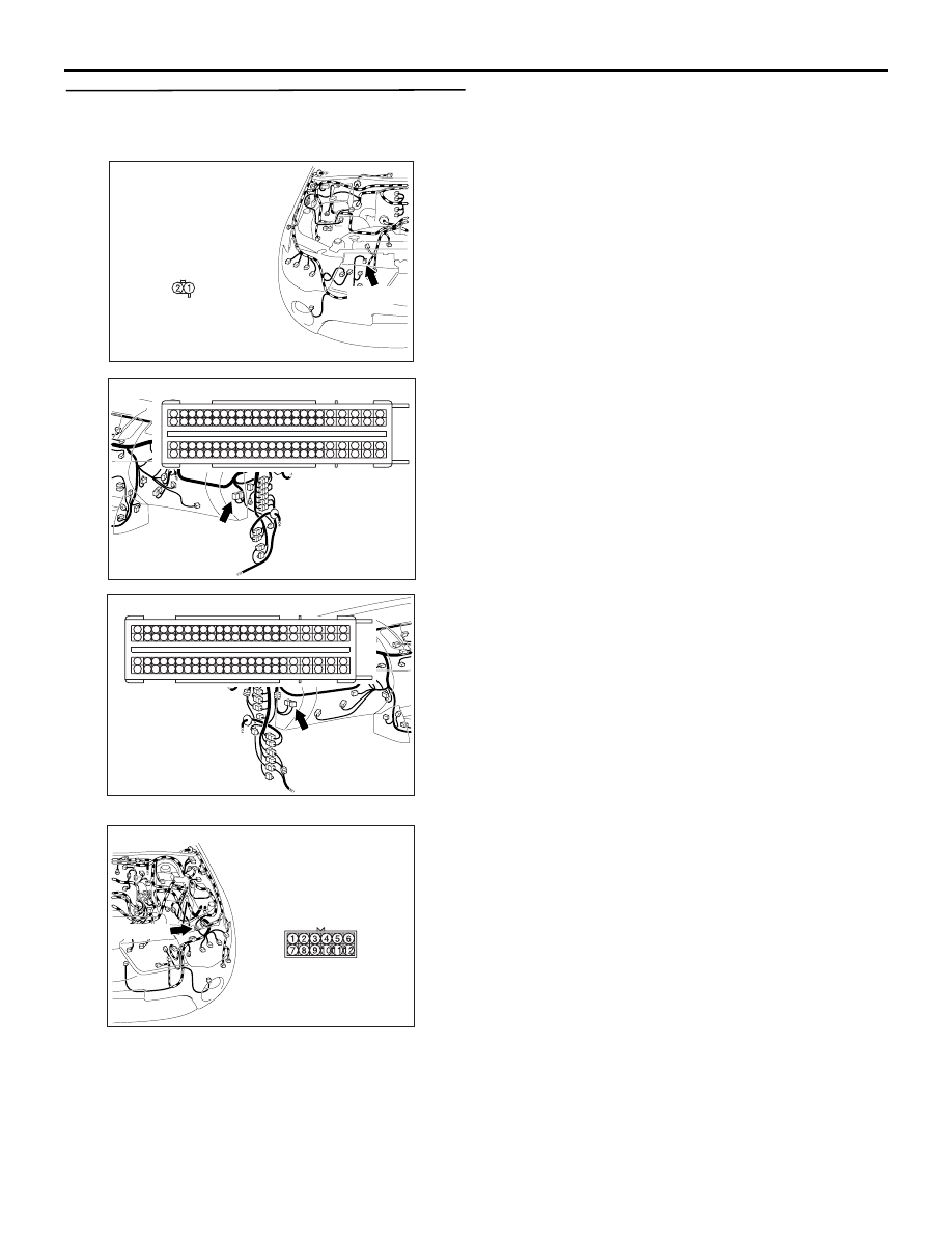
STEP 11. Check the wiring harness between C-
105 engine-ECU connector terminal No.8 and A-
38 dual pressure switch connector terminal No.1.

AC509977AG

Harness side

A-38 (BR)

Connector: A-38

AC509613 CD

Harness side

C-105 (B)

Connector: C-105 <LHD>

35

40

41

42

1817

38

39

15

16

14

3736

12

13

11

32

8

3433

9

10

30

31

7 6

29

5

4

28

3

27

2

26

1

25

19
43

2120

22

23

46

47

4544

24
48

76

52

86

62

63

64

65

66

67

68

69

70

71

72

92

95

96

93

94

89

90

91

8887

53

54

55

56

57

58

59

60

61

83

8584

8281

78

79

80

77

49

50

51

74

75

73

AC509930 CA

C-105 (B)

Connector: C-105 <RHD>

Harness side

35

40

41

42

1817

38

39

15

16

14

3736

12

13

11

32

8

3433

9

10

30

31

7 6

29

5

4

28

3

27

2

26

1

25

19
43

2120

22

23

46

47

4544

24
48

76

52

86

62

63

64

65

66

67

68

69

70

71

72

92

95

96

93

94

89

90

91

8887

53

54

55

56

57

58

59

60

61

83

8584

8281

78

79

80

77

49

50

51

74

75

73

NOTE: 

AC509975AH

Connector: A-28

A-28 (B)

Prior to the wiring harness inspection, check interme-
diate connector A-28, and repair if necessary.

• Check the input line for open circuit.

Q: Is the check result normal?

YES : 

Go to Step 12.

NO : 

Repair the wiring harness.

TROUBLESHOOTING

AUTOMATIC AIR CONDITIONER

55B-30

STEP 12. Check the wiring harness between C-
105 engine-ECU connector terminal No.13 and C-
43 A/C-ECU connector terminal No.16.

AC509977AG

Harness side

A-38 (BR)

Connector: A-38

AC509613

Connectors: C-53, C-105 <LHD>

CF

Harness side

C-105 (B)

35

40

41

42

1817

38

39

15

16

14

3736

12

13

11

32

8

3433

9

10

30

31

7 6

29

5

4

28

3

27

2

26

1

25

19
43

2120

22

23

46

47

4544

24
48

76

52

86

62

63

64

65

66

67

68

69

70

71

72

92

95

96

93

94

89

90

91

8887

53

54

55

56

57

58

59

60

61

83

8584

8281

78

79

80

77

49

50

51

74

75

73

C-53

C-53

Harness side

C-105

AC509930 CD

C-105 (B)

Connectors: C-35, C-105 <RHD>

Harness side

35

40

41

42

1817

38

39

15

16

14

3736

12

13

11

32

8

3433

9

10

30

31

7 6

29

5

4

28

3

27

2

26

1

25

19
43

2120

22

23

46

47

4544

24
48

76

52

86

62

63

64

65

66

67

68

69

70

71

72

92

95

96

93

94

89

90

91

8887

53

54

55

56

57

58

59

60

61

83

8584

8281

78

79

80

77

49

50

51

74

75

73

C-35

Harness side

C-105

C-53

AC509611AR

Connector: C-43 <LHD>

Harness side

AC509932AS

Harness side

Connector: C-43 <RHD>

TROUBLESHOOTING

AUTOMATIC AIR CONDITIONER

55B-31

NOTE: Prior to the wiring harness inspection, check 
intermediate connector C-53 <LHD> or C-35 <RHD> 
and repair if necessary.

• Check the input line for open circuit.

Q: Is the check result normal?

YES : 

Go to Step 13.

NO : 

Repair the wiring harness.

STEP 13. Check the refrigerant level.
 Refer to .

Q: Is the refrigerant level correct?

YES : 

Go to Step 14.

NO : 

Correct the refrigerant level (Refer to On-
vehicle Service .)

STEP 14. Replace the A/C-ECU, and then recheck 
the trouble symptom
 Check that the compressor works normally.

Q: Is the check result normal?

YES : 

This diagnosis is complete.

NO : 

Replace the engine-ECU.

TROUBLESHOOTING

AUTOMATIC AIR CONDITIONER

55B-32

Inspection Procedure 2: The blower does not work

Blower Motor Circuit

FUSIBLE
LINK

20

IGNITION
SWITCH (IG2)

BLOWER
RELAY

A/C-ECU

BLOWER
MOTOR

POWER
TRANSISTER

Wire colour code
B : Black     LG : Light green     G : Green     L : Blue     W : White     Y : Yellow     SB : Sky blue
BR : Brown     O : Orange     GR : Grey     R : Red     P : Pink     V : Violet     PU : Purple

AC805774 AB

COMMENTS ON TROUBLE SYMPTOM
If the blower motor does not operate, the blower 
motor circuit system may be defective.

POSSIBLE CAUSES

• Malfunction of the blower relay

• Malfunction of the blower motor

• Damaged the wiring harness or connectors

DIAGNOSIS PROCEDURE

STEP 1. Check that the blower motor operates 
when the blower speed selection dial is moved to 
the "MAX " position.
(1) Turn the ignition switch to the "ON" position.
(2) Turn the blower speed selection dial to the "MAX 


Content   ..  873  874  875  876   ..