Mitsubishi L200. Manual - part 876


  Index      Mitsubishi     Mitsubishi L200 - service repair manual 2012 year


Search            


Content   ..  874  875  876  877   ..


Mitsubishi L200. Manual - part 876


TROUBLESHOOTING

AUTOMATIC AIR CONDITIONER

55B-33

" position.

Q: Does the blower motor operate when the blower 

speed selection dial is moved to the "MAX " 
position?
YES : 

Refer to Inspection procedure 3 "The blower 

air volume cannot be changed 

P.55B-41

."

NO : 

Go to Step 2.

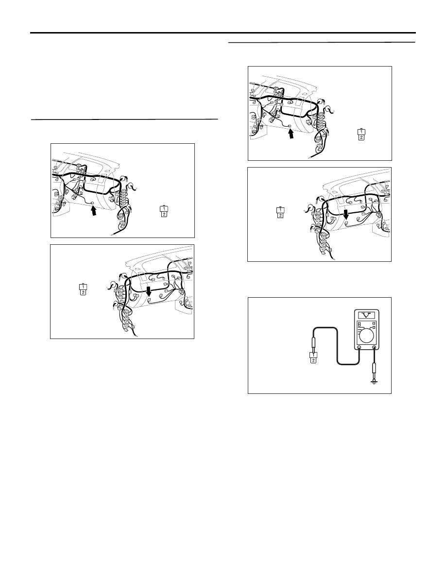
STEP 2. Connector check: C-28 blower motor 
connector

AC509613AS

Harness side

Connector: C-28 <LHD>

AC509930AR

Harness side

Connector: C-28 <RHD>

Q: Is the check result normal?

YES : 

Go to Step 3.

NO : 

Repair the connector.

STEP 3. Voltage measurement at C-28 blower 
motor connector.

AC509613AS

Harness side

Connector: C-28 <LHD>

AC509930AR

Harness side

Connector: C-28 <RHD>

(1) Disconnect the connector, and measure at the 

wiring harness side.

(2) Turn the ignition switch to the "ON" position.

AC310507 JK

Connector C-28 
(Harness side)

(3) Measure the voltage between terminal 1 and 

body earth.

OK: System voltage

Q: Is the check result normal?

YES : 

Go to Step 13.

NO : 

Go to Step 4.

TROUBLESHOOTING

AUTOMATIC AIR CONDITIONER

55B-34

STEP 4. Connector check: C-201 blower relay 
connector

AC509934AT

Connector: C-201 <LHD>

Junction block side

Junction block (Front view)

AC509936AP

Connector: C-201 <RHD>

Junction block side

Junction block (Front view)

Q: Is the check result normal?

YES : 

Go to Step 5.

NO : 

Repair the connector. 

STEP 5. Check the blower relay continuity.
 Refer to .

Q: Is the blower relay continuity in good condition?

YES : 

Go to Step 6.

NO : 

Replace the blower relay.

STEP 6. Voltage measurement at C-201 blower 
relay connector.

AC509934AT

Connector: C-201 <LHD>

Junction block side

Junction block (Front view)

AC509936AP

Connector: C-201 <RHD>

Junction block side

Junction block (Front view)

(1) Remove the relay, and measure at the junction 

block side.

(2) Turn the ignition switch to the "ON" position.

AC310507 JL

Connector C-201 
(Junction block side)

(3) Measure the voltage between terminal 1 and 

earth.

OK: System voltage

Q: Is the check result normal?

YES : 

 Go to Step 8.

NO : 

Go to Step 7.

TROUBLESHOOTING

AUTOMATIC AIR CONDITIONER

55B-35

STEP 7. Check the wiring harness between C-201 
blower relay connector terminal No.1 and the 
ignition switch (IG2).

AC509934AT

Connector: C-201 <LHD>

Junction block side

Junction block (Front view)

AC509936AP

Connector: C-201 <RHD>

Junction block side

Junction block (Front view)

NOTE: 

AC509936

Connector: C-207 <RHD>

Harness side

BB

Junction block 
(Front view)

AC509934

Connector: C-207 <LHD>

BE

Junction 

block

Junction block side

Prior to the wiring harness inspection, check junction 
block connector C-207, and repair if necessary.

• Check the blower relay power supply line for 

open circuit.

Q: Is the check result normal?

YES : 

The trouble can be an intermittent 

malfunction (Refer to GROUP 00, How to 
Cope with Intermittent Malfunction ).

NO : 

Repair the wiring harness.

STEP 8. Measure the voltage at C-201 blower 
relay connector.

AC509934AT

Connector: C-201 <LHD>

Junction block side

Junction block (Front view)

AC509936AP

Connector: C-201 <RHD>

Junction block side

Junction block (Front view)

(1) Remove the relay, and measure at the junction 

block side.

AC310507JM

Connector C-201
(Junction block side)

(2) Measure the voltage between terminal 4 and 

body earth.

OK: System voltage

Q: Is the check result normal?

YES : 

 Go to Step 10.

NO : 

Go to Step 9.   

TROUBLESHOOTING

AUTOMATIC AIR CONDITIONER

55B-36

STEP 9. Check the wiring harness between C-201 
blower relay connector terminal No.4 and fusible 
link (20).

AC509934 AW

Connectors: C-201, C-213 <LHD>

Junction block side

Junction block (Front view)

C-201

Harness side

C-213

C-201

C-213

AC509936AS

Connectors: C-201, C-213 <RHD>

Junction block side

Junction block (Front view)

C-201

Harness side

C-213

C-201

C-213

NOTE: Prior to the wiring harness inspection, check 
junction block connector C-213, and repair if neces-
sary.

• Check the blower relay power supply line for 

open circuit.

Q: Is the check result normal?

YES : 

The trouble can be an intermittent 

malfunction (Refer to GROUP 00, How to 
Cope with Intermittent Malfunction ).

NO : 

Repair the wiring harness.

STEP 10. Resistance measurement at the C-201 
blower relay connector.

AC509934AT

Connector: C-201 <LHD>

Junction block side

Junction block (Front view)

AC509936AP

Connector: C-201 <RHD>

Junction block side

Junction block (Front view)

(1) Disconnect the connector, and measure at the 

wiring harness side.

AC310506IA

Connector C-201 
(Harness side)

(2) Measure the resistance between terminal 2 and 

body earth.

OK: Continuity (Less than 2

)

Q: Is the check result normal?

YES : 

Go to Step 12.

NO : 

Go to Step 11.


Content   ..  874  875  876  877   ..