Mitsubishi L200. Manual - part 842
TROUBLESHOOTING
CONTROLLER AREA NETWORK (CAN)
54C-127
DIAGNOSIS PROCEDURE
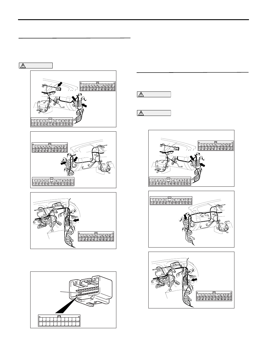
STEP 1. Connector check: C-53 <LHD> or C-35
<RHD> intermediate connector, C-119 joint
connector (CAN1) and C-01 joint connector
(CAN2)
AC903853
BR
Connectors: C-01, C-53, C-119 <LHD>
C-01 (L)
C-53
C-119 (GR)
C-53
C-01, C-119
AC903865AW
Connectors: C-01, C-35 <RHD>
C-01 (L)
C-35
C-01
C-35
AC903868
CM
Connector: C-119 <RHD>
C-119 (GR)
CAUTION
The strand end of the twist wire should be within
10 cm from the connector. For details refer to
.
AC209350
1
12
2
13
3
14
4
15
5
16
6
17
7
18
8
19
9
20
10
21
11
22
AC209350
1
12
2
13
3
14
4
15
5
16
6
17
7
18
8
19
9
20
10
21
11
22
AC
Short pin
When checking the joint connector, ensure that its
wiring harness side and its short pins are not dam-
aged.
Q: Is the check result normal?
YES :
Go to Step 2.
NO :
Repair the defective connector. Replace the
joint connector as necessary.
STEP 2. Resistance measurement at C-119 joint
connector (CAN1) and C-53 <LHD> or C-35
<RHD> intermediate connector.
CAUTION
A digital multimeter should be used. For details
refer to
CAUTION
The test wiring harness should be used. For
details refer to
.
AC903853
BS
Connectors: C-53, C-119 <LHD>
C-53
C-119 (GR)
C-53
C-119
AC903865
Connector: C-35 <RHD>
AQ
AC903868
CM
Connector: C-119 <RHD>
C-119 (GR)
(1) Disconnect the joint connector (CAN1) and the
intermediate connector, and measure at the
wiring harness side.
(2) Turn the ignition switch to the LOCK (OFF)