Mitsubishi L200. Manual - part 838


  Index      Mitsubishi     Mitsubishi L200 - service repair manual 2012 year


Search            


Content   ..  836  837  838  839   ..


Mitsubishi L200. Manual - part 838


TROUBLESHOOTING

CONTROLLER AREA NETWORK (CAN)

54C-111

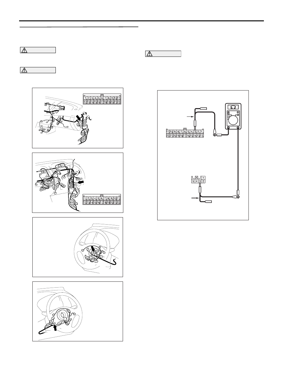
STEP 2. Resistance measurement at C-119 joint 
connector (CAN1) and C-308 steering wheel 
sensor connector.

CAUTION

A digital multimeter should be used. For details 
refer to 

P.54C-7

.

CAUTION

The test wiring harness should be used. For 
details refer to 

P.54C-7

.

AC903853

BM

Connector: C-119 <LHD>

C-119 (GR)

AC903868

CM

Connector: C-119 <RHD>

C-119 (GR)

AC903858

Connector: C-308 <LHD>

AK

AC903869

Connector: C-308 <RHD>

AK

(1) Disconnect joint connector (CAN1) and the 

steering wheel sensor connector, and measure at 
the wiring harness side.

(2) Turn the ignition switch to the LOCK (OFF) 

position.

CAUTION

When measuring the resistance, disconnect the 
negative battery terminal. For details refer to 

P.54C-7

.

(3) Ensure that the negative battery terminal is 

disconnected.

AC204740

AC204740

AC204740

Harness side: C-308

Harness side: C-119

HX

Test 
harness

Test 
harness

(4) Continuity between C-119 joint connector (CAN1) 

terminal No.3 and C-308 steering wheel sensor 

TROUBLESHOOTING

CONTROLLER AREA NETWORK (CAN)

54C-112

connector terminal No.3

OK: Continuity (2 

 or less) 

AC204740

AC204740

AC204740

Harness side: C-308

AC204740

AC204740

Harness side: C-119

HY

Test 
harness

Test 
harness

(5) Continuity between C-119 joint connector (CAN1) 

terminal No.14 and C-308 steering wheel sensor 
connector terminal No.4

OK: Continuity (2 

 or less) 

CAUTION

Strictly observe the specified wiring harness 
repair procedure. For details refer to 

P.54C-7

.

Q: Is the check result normal?

YES : 

<All the resistances measure 2 

Ω or less> 

Power supply to the steering wheel sensor 
may be suspected. Diagnose the steering 
wheel sensor. Refer to .

NO  : 

<Either or all of the resistances measure 
more than 2 

Ω> Repair the wiring harness 

between joint connector (CAN1) and the 
steering wheel sensor connector.

TROUBLESHOOTING

CONTROLLER AREA NETWORK (CAN)

54C-113

Diagnosis Item 9: Diagnose when the M.U.T.-III cannot receive the data sent by G and yaw rate sensor. 
<vehicles with ASTC>

CAUTION

When servicing a CAN bus line, earth yourself by touching a metal object such as an unpainted water 
pipe. If you fail to do, a component connected to the CAN bus line may be broken.

Wire colour code 
B : Black     LG : Light green     G : Green     L : Blue     W : White 
Y : Yellow     SB : Sky blue     BR : Brown     O : Orange     GR : Grey 
R : Red     P : Pink     V : Violet     PU : Purple     SI : Silver

A/T-ECU

DIAGNOSIS 
CONNECTOR

ENGINE-ECU

STEERING 
WHEEL 
SENSOR

G AND 
YAW RATE 
SENSOR

A/C-ECU

ABS-ECU

ASTC-ECU

ETACS-ECU

RV METER

NOTE

:VEHICLES WITH ABS
:VEHICLES WITH ASTC
:VEHICLES WITH RV METER
:VEHICLES WITH AUTOMATIC-A/C
:LHD
:RHD
:A/T

TROUBLESHOOTING

CONTROLLER AREA NETWORK (CAN)

54C-114

FUNCTION
The diagnostic result demonstrates that "the M.U.T.-
III cannot receive the sent data from the G and yaw 
rate sensor" when the M.U.T.-III checks the periodi-
cally sent data from each ECU.

TROUBLE JUDGEMENT CONDITIONS
M.U.T.-III judges the trouble when the periodically 
sent data from G and yaw rate sensor cannot be 
received. 


Content   ..  836  837  838  839   ..