Mitsubishi L200. Manual - part 836


  Index      Mitsubishi     Mitsubishi L200 - service repair manual 2012 year


Search            


Content   ..  834  835  836  837   ..


Mitsubishi L200. Manual - part 836


TROUBLESHOOTING

CONTROLLER AREA NETWORK (CAN)

54C-103

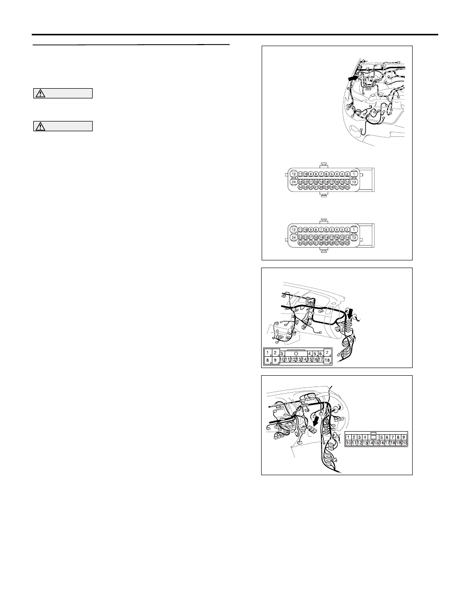
STEP 3. Resistance measurement at C-13 
intermediate connector and A-01 ABS-ECU 
<vehicles with ABS> or A-48 ASTC-ECU 
<vehicles with ASTC> connector.

CAUTION

A digital multimeter should be used. For details 
refer to 

P.54C-7

.

CAUTION

The test wiring harness should be used. For 
details refer to 

P.54C-7

.

AC903990

Connectors: A-01, A-48

AB

A-01 (GR) 
A-48 (B)

Harness side

A-01

Harness side

A-48

AC903853

BP

Connector: C-13 <LHD>

AC903868

Connector: C-13 <RHD>

AX

(1) Disconnect the intermediate connector and the 

ABS-ECU <vehicles with ABS> or ASTC-ECU 
<vehicles with ASTC> connector, and measure at 
the wiring harness side.

(2) Turn the ignition switch to the LOCK (OFF) 

TROUBLESHOOTING

CONTROLLER AREA NETWORK (CAN)

54C-104

position.

CAUTION

When measuring the resistance, disconnect the 
negative battery terminal. For details refer to 

P.54C-7

.

(3) Ensure that the negative battery terminal is 

disconnected.

AC204740

Harness side: A-01

ON

Test 
harness

Test 
harness

Harness side: C-13

(4) Continuity between C-13 intermediate connector 

terminal No.15 and A-01 ABS-ECU connector 

terminal No.23 <LHD-vehicles with ABS>

OK: Continuity (2 

 or less) 

AC204740

Harness side: A-01

OO

Test 
harness

Test 
harness

Harness side: C-13

(5) Continuity between C-13 intermediate connector 

terminal No.12 and A-01 ABS-ECU connector 
terminal No.23 <RHD-vehicles with ABS>

OK: Continuity (2 

 or less) 

AC204740

Harness side: A-48

OP

Test 
harness

Test 
harness

Harness side: C-13

(6) Continuity between C-13 intermediate connector 

terminal No.15 and A-48 ASTC-ECU connector 

TROUBLESHOOTING

CONTROLLER AREA NETWORK (CAN)

54C-105

terminal No.23 <LHD-vehicles with ASTC>

OK: Continuity (2 

 or less) 

AC204740OQ

Test 
harness

Harness side: C-13

Harness side: A-48

Test 
harness

(7) Continuity between C-13 intermediate connector 

terminal No.12 and A-48 ASTC-ECU connector 
terminal No.23 <RHD-vehicles with ASTC>

OK: Continuity (2 

 or less) 

AC204740

Harness side: A-01

OR

Test 
harness

Test 
harness

Harness side: C-13

(8) Continuity between C-13 intermediate connector 

terminal No.14 and A-01 ABS-ECU connector 

terminal No.34 <LHD-vehicles with ABS>

OK: Continuity (2 

 or less) 

AC204740

Harness side: A-01

OS

Test 
harness

Test 
harness

Harness side: C-13

(9) Continuity between C-13 intermediate connector 

terminal No.13 and A-01 ABS-ECU connector 
terminal No.34 <RHD-vehicles with ABS>

OK: Continuity (2 

 or less) 

AC204740

AC204740

Harness side: A-48

OT

Test 
harness

Test 
harness

Harness side: C-13

(10)Continuity between C-13 intermediate connector 

terminal No.14 and A-48 ASTC-ECU connector 

TROUBLESHOOTING

CONTROLLER AREA NETWORK (CAN)

54C-106

terminal No.34 <LHD-vehicles with ASTC>

OK: Continuity (2 

 or less) 

AC204740

Harness side: A-48

OU

Test 
harness

Test 
harness

Harness side: C-13

(11)Continuity between C-13 intermediate connector 

terminal No.13 and A-48 ASTC-ECU connector 
terminal No.34 <RHD-vehicles with ASTC>

OK: Continuity (2 

 or less) 

CAUTION

Strictly observe the specified wiring harness 
repair procedure. For details refer to 

P.54C-7

.

Q: Is the check result normal?

YES : 

<All the resistances measure 2 

Ω or less> 

Power supply to the ABS-ECU <vehicles 
with ABS> or ASTC-ECU <vehicles with 
ASTC> may be suspected. Diagnose the 
ABS or ASTC. Refer to  <vehicles with 
ABS> or  <vehicles with ASTC>.

NO  : 

<Either or all of the resistances measure 
more than 2 

Ω> Repair the wiring harness 

between intermediate connector (C-13) and 
the ABS-ECU <vehicles with ABS> or 
ASTC-ECU <vehicles with ASTC> 
connector.


Content   ..  834  835  836  837   ..