Mitsubishi L200. Manual - part 813
EXPLANATION ABOUT THE M.U.T.-III CAN BUS DIAGNOSTICS
CONTROLLER AREA NETWORK (CAN)
54C-11
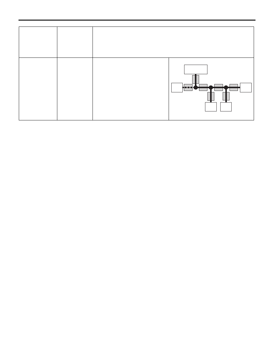
ECU which
cannot
communicate
with the
M.U.T.-III
Possible
trouble spot
Logic for narrowing down trouble spot
ECU A
CAN bus line
(a) and power
supply system
to ECU A
ECU A communicates with the
M.U.T.-III via CAN bus lines (a)
and (b). The M.U.T.-III judges that
CAN bus line (b) is normal,
because it can communicate with
other ECUs. Possible trouble may
be present in CAN bus line (a) or
the power supply system to ECU
A.
AC204742 AZ
Diagnosis
connector
ECU B
ECU C
ECU D
ECU A
(a)
(b)
(c)
(d)
(e)
(f)
(g)