Mitsubishi L200. Manual - part 814
ACA01245
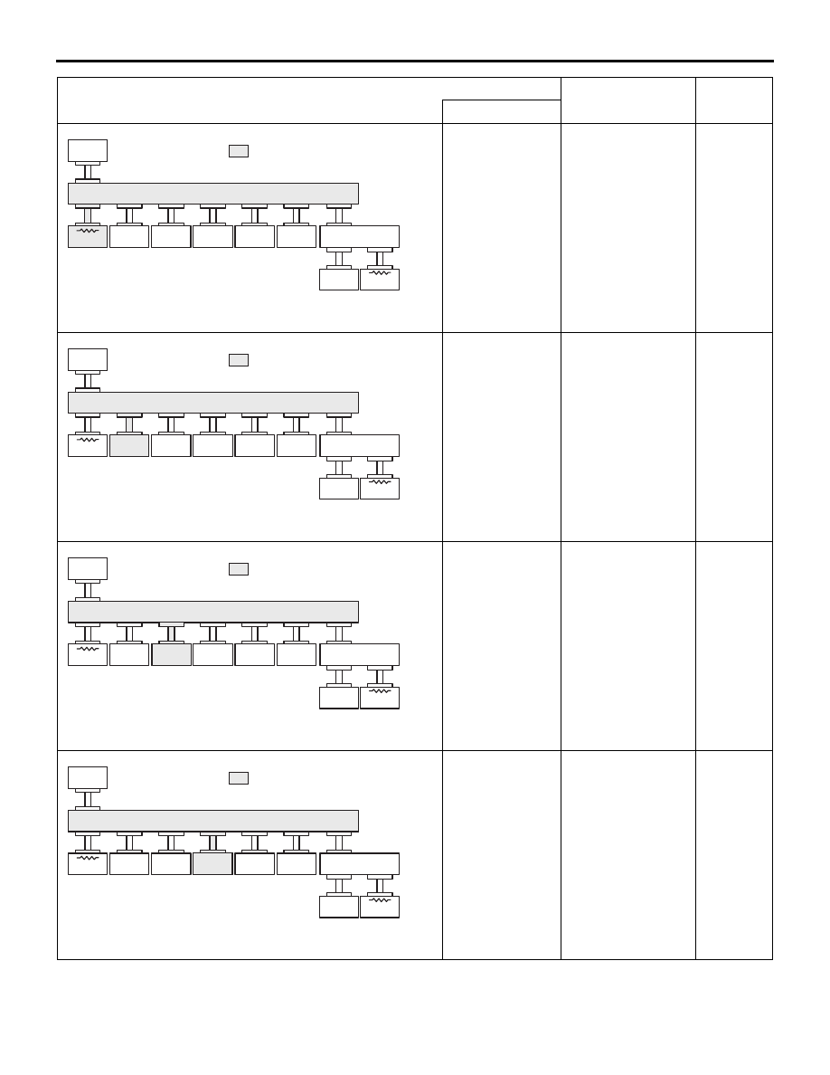
: Red section on screen
AD
ETACS
DISPLAY
ABS/ASC
SAS
YR/G
A/C
AT
ENGINE
JC
JC
M.U.T.
TROUBLESHOOTING
CONTROLLER AREA NETWORK (CAN)
54C-15
Harness
disconnection or
loose
connection in
red displayed
area is
estimated.
Diagnosis Item 5
Diagnose when
the M.U.T.-III
cannot receive the
data sent by
ETACS-ECU.
ACA01245
: Red section on screen
AE
ETACS
DISPLAY
ABS/ASC
SAS
YR/G
A/C
AT
ENGINE
JC
JC
M.U.T.
Harness
disconnection or
loose
connection in
red displayed
area is
estimated.
Diagnosis Item 6
Diagnose when
the M.U.T.-III
cannot receive the
data sent by RV
meter <vehicles
with RV meter>.
ACA01245
: Red section on screen
AF
ETACS
DISPLAY
ABS/ASC
SAS
YR/G
A/C
AT
ENGINE
JC
JC
M.U.T.
Harness
disconnection or
loose
connection in
red displayed
area is
estimated.
Diagnosis Item 7
Diagnose when
the M.U.T.-III
cannot receive the
data sent by ABS-
ECU <Vehicles
with ABS> or
ASTC-ECU
<Vehicles with
ASTC>
ACA01245
: Red section on screen
AG
ETACS
DISPLAY
ABS/ASC
SAS
YR/G
A/C
AT
ENGINE
JC
JC
M.U.T.
Harness
disconnection or
loose
connection in
red displayed
area is
estimated.
Diagnosis Item 8
Diagnose when
the M.U.T.-III
cannot receive the
data sent by
steering wheel
sensor <Vehicles
with ASTC>
M.U.T.-III screen
Diagnosis detail
Referenc
e page
(The ECUs that are not adopted are not displayed.)
Comment