Mitsubishi L200. Manual - part 755


  Index      Mitsubishi     Mitsubishi L200 - service repair manual 2012 year


Search            


Content   ..  753  754  755  756   ..


Mitsubishi L200. Manual - part 755


STEERING WHEEL AUDIO REMOTE CONTROL SWITCH

CHASSIS ELECTRICAL

54A-387

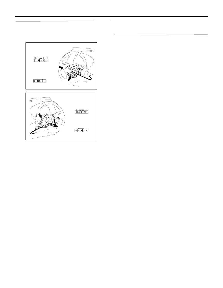
STEP 7. Check the wiring harness between C-311 
steering wheel audio remote control switch 
connector terminal No.2, 4 and C-310 clock 
spring connector terminal No.5, 4.

• Check the communication lines for open and 

short circuit.

Q: Is the check result normal?

YES : 

Go to Step 8.

NO : 

Repair the wiring harness.

STEP 8. Retest the system
Check whether you can operate the radio and CD 
player by using the steering wheel audio remote con-
trol switch.

Q: Is the check result normal?

YES : 

The trouble can be an intermittent 

malfunction (Refer to GROUP 00 

− How to 

Use Troubleshooting/inspection Service 
Points 

− How to Cope with Intermittent 

Malfunction ).

NO : 

Replace the radio and CD player.

AC903858AI

Connectors: C-310, C-311 <LHD>

C-310

Harness side

C-310

C-311

Harness side

C-311 (R)

AC903869 AI

Connectors: C-310, C-311 <RHD>

Harness side

C-311

C-311 (R)

C-310

Harness side

C-310

STEERING WHEEL AUDIO REMOTE CONTROL SWITCH

CHASSIS ELECTRICAL

54A-388

Inspection Procedure 1: Steering wheel audio remote control switch does not function. <Vehicle with 
MMCS>

TECHNICAL DESCRIPTION (COMMENT)
The power supply circuit to the steering wheel audio 
remote control switch, the steering wheel audio 
remote control switch, the multivision display, or the 
clock spring may be defective.

TROUBLESHOOTING HINTS

• Malfunction of steering wheel audio remote con-

trol switch

• Malfunctions of multivision display

• Malfunction of the clock spring

• Damaged harness wires and connectors

Steering Wheel Audio Remote Control Switch Circuit

MULTIVISION DISPLAY

CLOCK 
SPRING

STEERING 
WHEEL AUDIO
REMOTE 
CONTROL 
SWITCH

Wire colour code 
B : Black     LG : Light green     G : Green     L : Blue     W : White     Y : Yellow     SB : Sky blue 
BR : Brown     O : Orange     GR : Grey     R : Red     P : Pink     V : Violet     PU : Purple     SI : Silver

STEERING WHEEL AUDIO REMOTE CONTROL SWITCH

CHASSIS ELECTRICAL

54A-389

DIAGNOSIS PROCEDURE

STEP 1. Connector check: C-311 steering wheel 
audio remote control switch connector

Q: Is the check result normal?

YES : 

Go to Step 2.

NO : 

Repair the defective connector.

STEP 2. Check the steering wheel audio remote 
control switch.
Check the continuity of the steering wheel audio 
remote control switch. (Refer to 

P.54A-397

).

Q: Is the hood switch in good condition?

YES : 

Go to Step 3.

NO : 

Replace the steering wheel audio remote 
control switch.

STEP 3. Connector check: C-310 and C-306 clock 
spring connector

Q: Is the hood switch in good condition?

YES : 

Go to Step 4.

NO : 

Repair the defective connector.

STEP 4. Check the clock spring.
Check whether the clock spring is in good condition 
(Refer to GROUP 52B 

− Air bag module and clock 

spring ).

• Check if continuity exists between C-310 clock 

spring connector terminal No.4 and C-306 clock 
spring connector terminal No.3.

• Check if continuity exists between C-310 clock 

spring connector terminal No.5 and C-306 clock 
spring connector terminal No.2.

Q: Is the check result normal?

YES : 

Go to Step 5.

NO : 

Replace the clock spring.

AC903858 AF

Connector: C-311 <LHD>

Harness side

C-311 (R)

AC903869 AF

Connector: C-311 <RHD>

Harness side

C-311 (R)

AC903858AG

Connectors: C-306, C-310 <LHD>

Harness side

C-306 (B)

C-310

C-306

Harness side

C-310

AC903869AG

Connectors: C-306, C-310 <RHD>

Harness side

C-306 (B)

C-310

C-306

Harness side

C-310

STEERING WHEEL AUDIO REMOTE CONTROL SWITCH

CHASSIS ELECTRICAL

54A-390

STEP 5. Connector check: C-167 multivision 
display connector

Q: Is the check result normal?

YES : 

Go to Step 6.

NO : 

Repair the defective connector.

STEP 6. Check the wiring harness between C-167 
multivision display connector terminal No.59, 43 
and C-306 clock spring connector terminal No.3, 
2.

• Check the communication lines for open and 

short circuit.

Q: Is the check result normal?

YES : 

Go to Step 7.

NO : 

Repair the wiring harness.

AC903856AS

Connector: C-167 <LHD>

C-167 (GR)

Harness side

AC903865

Harness side

AJ

Connector: C-167 <RHD>

AC903856AS

Connector: C-167 <LHD>

C-167 (GR)

Harness side

AC903865

Harness side

AJ

Connector: C-167 <RHD>

AC903858AH

Connector: C-306 <LHD>

Harness side

C-306 (B)

AC903869AH

Connector: C-306 <RHD>

Harness side

C-306 (B)


Content   ..  753  754  755  756   ..