Mitsubishi L200. Manual - part 754
STEERING WHEEL AUDIO REMOTE CONTROL SWITCH
CHASSIS ELECTRICAL
54A-383
SPECIAL TOOLS
M1544000600652
TROUBLESHOOTING
STANDARD FLOW OF DIAGNOSTIC
TROUBLESHOOTING
M1544004800551
Refer to GROUP 00
− Contents of troubleshooting .
TROUBLE SYMPTOM CHART
M1544004901863
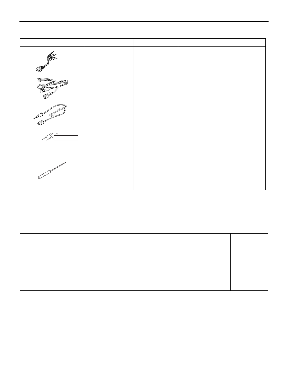
Tool
Number
Name
Use
MB991223
a. MB991219
b. MB991220
c. MB991221
d. MB991222
Harness set
a. Check harness
b. LED harness
c. LED harness
adapter
d. Probe
Continuity check and voltage
measurement at harness wire or
connector
a. For checking connector pin
contact pressure
b. For checking power supply circuit
c. For checking power supply circuit
d. For connecting a locally sourced
tester
MB992006
Extra fine probe
Continuity check and voltage
measurement at harness wire or
connector
MB991223
a
d
c
b
DO NOT USE
BA
MB992006
Inspection
Procedure
No.
Trouble symptom
Reference
page
1
Steering wheel audio remote control switch does not
function.
<Vehicle with radio
and CD player>
Steering wheel audio remote control switch does not
function.
<Vehicle with MMCS>
2
Steering wheel audio remote control switch illumination does not come on.