Mitsubishi L200. Manual - part 732


  Index      Mitsubishi     Mitsubishi L200 - service repair manual 2012 year


Search            


Content   ..  730  731  732  733   ..


Mitsubishi L200. Manual - part 732


RADIO AND CD PLAYER

CHASSIS ELECTRICAL

54A-295

<USING SPECIAL TOOL>

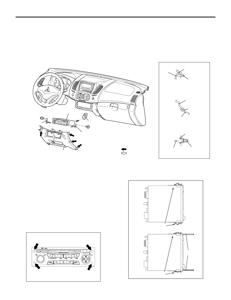
REMOVAL SERVICE POINT

<<A>> RADIO AND CD PLAYER REMOVAL
Using the special tool audio remover and installer 
(MB992279), the radio and CD player can be 
removed without removing the lower panel assembly.

1. Insert the special tool audio remover and installer 

(MB992279) into the service hole of radio and CD 
player.

Removal steps 

Lower panel assembly (Refer to 
GROUP 52A, Instrument Panel 
Assembly ).

1.

Centre lower panel

2.

Radio and CD player

3.

DIN guide

4.

DIN bracket

Removal steps (Continued)

AC508514

3

B

B

A

A

1

4

1

Section A – A

Claw

Centre upper 
panel

Section B – B

Claw

Centre upper 

panel

Section C – C

Clip

Instrument 

panel

AB

3

2

1

1

NOTE
(1)         : Clip positions
(2)         : Claw positions

C

C

Removal Steps 

<<

A

>>

>>

A

<<

1.

Radio and CD player

Lower panel assembly (Refer to 
GROUP 52A, Instrument Panel 
Assembly ).

2.

Centre lower panel

3.

DIN guide

4.

DIN bracket

ACB01999AC

AC801156

MB992279

Claw

Claw

AJ

RADIO AND CD PLAYER

CHASSIS ELECTRICAL

54A-296

2. Press in the claws of radio and CD player using 

the special tool audio remover and installer 
(MB992279).

3. After pulling out the radio and CD player, 

disconnect the connector connection.

INSTALLATION SERVICE POINT

>>A<< RADIO AND CD PLAYER INSTALLATION

Press the radio and CD player using the special tool 
audio remover and installer (MB992279).

REMOVAL AND INSTALLATION

M1544019400021

INSPECTION

AUDIO ADAPTER INSPECTION

M1544019000197

1. Remove the audio adapter.(Refer to 

P.54A-296

)

2. Check that the continuity exists between the pin 

jack of audio adapter and terminals.

AC805685AB

MB992279

AC805685AC

MB992279

AC809004

AB

1

2

Rear floor console assembly

Removal Steps 

Rear floor console assembly (Refer 
to GROUP 52A, floor console 
assembly ).

1.

Front console harness

2.

Audio adapter

MITSUBISHI MULTI COMMUNICATION SYSTEM (MMCS)

CHASSIS ELECTRICAL

54A-297

MITSUBISHI MULTI COMMUNICATION SYSTEM (MMCS)

GENERAL INFORMATION

M1544000101111

Mitsubishi multi-communication system (multivision 
display) with built-in hard disk drive (40 gigabyte) has 
been installed. Also, a 7-inch liquid crystal display of 
wide 2 DIN size has been adopted.

• The NAVTEQ map data (large volume map data 

for Europe) has been stored. <Except vehicle for 
RUSSIA>

• The Mitsubishi multi-communication system with 

NAVTEQ map data (large volume map data for 
RUSSIA) and the Mitsubishi multi-communication 
system without NAVTEQ map data are available. 
<Vehicle for RUSSIA>

•  The 7-inch wide liquid crystal monitor has been 

adopted. The operation switch for operability has 
been equipped.

• Most sophisticated LSI* has been used as one for 

car navigation system.

NOTE: *:LSI stands for Large Scale Integration, and 

is a large-scale integrated circuit (IC) containing 
between 1,000 and 100,000 circuit elements. 

• It is compatible with nine languages (English, 

Germany, French, Spanish, Italian, Portuguese, 
Dutch, Swedish and Danish). <Except vehicle for 
RUSSIA>

• The multivision display for Russia corresponds to 

Russian only.<Vehicle for RUSSIA>

• Compatible with RDS function.

In order to connect video equipment such as video 

computer and video player, the external connec-
tion jacks (audio and video adapter) has been 
installed to the rear floor console.

AC903739

AUDIO

L (MONO)

AUDIO

R

Red

White

1

2

3

4

Pin Jack 

Pin Jack 

AB

The connection position 
of pin jack side circuit 
tester

Terminal 
number

Measurem
ent value

1

5

Continuity 
exists (2 

Ω 

or less)

2

4

3

5

4

6

AC903657AB

Multivision display

AC809012

AD

Audio and video
 adopter

Rear floor console

MITSUBISHI MULTI COMMUNICATION SYSTEM (MMCS)

CHASSIS ELECTRICAL

54A-298

• An exclusive tuner for TMC is incorporated.

• Control by steering wheel audio remote control 

switch

SYSTEM BLOCK DIAGRAM

Screen (function)

Contents

Navigation screen 

Displays navigation functions such as road map, search, guidance and 
information retrieval.

Screen of current vehicle 
location

Information on vehicle's current position (such as latitude, longitude, altitude 
and GPS reception status)

CD/DVD

Plays the CD or DVD inserted to the drive (Designed for MP3/WMA file)

Music server screen

Plays music recorded in the hard disk drive and records a music CD. (The 
title whose information is acquired from CDDB can be displayed.)

Sound control

Adjusts the high/middle/low tone and balance. Function to set Equalizer type, 
sound field, and others when adopting the ROCKFORD

™ ACOUSTIC 

DESIGN PREMIUM SOUND SYSTEM

Radio screen

Displays available broadcast stations and channels. FM(RDS)/MW/LW

AUX

Plays the image and sound input through the audio and video adapter. 
(Image cannot be seen during driving because of the driving restriction.)

AC903659

Multivision display

GPS antenna

Radio antenna

Sound

Steering wheel 
audio remote control switch

Audio amplifier

Speaker

Audio and 
video adapter

Sound

Image

Speaker

<Vehicles with 
 audio amplifier>

<Vehicles without 
 audio amplifier>

AB

Steering wheel 
voice control switch


Content   ..  730  731  732  733   ..