Mitsubishi L200. Manual - part 700


  Index      Mitsubishi     Mitsubishi L200 - service repair manual 2012 year


Search            


Content   ..  698  699  700  701   ..


Mitsubishi L200. Manual - part 700


REAR FOG LAMP

CHASSIS ELECTRICAL

54A-167

SYMPTOM PROCEDURES

Inspection Procedure 1: The rear fog lamp do not illuminate normally.

CAUTION

Whenever the ECU is replaced, ensure that the 
input and output signal circuits are normal.

COMMENTS ON TROUBLE SYMPTOM
If the rear fog lamp do not illuminate, the wiring har-
ness connector(s), the bulb or the fuse may be 
defective. Otherwise the input signal circuit(s) below 
or the ETACS-ECU may be defective.

• Tail lamp switch

• Headlamp switch

• Rear fog lamp switch

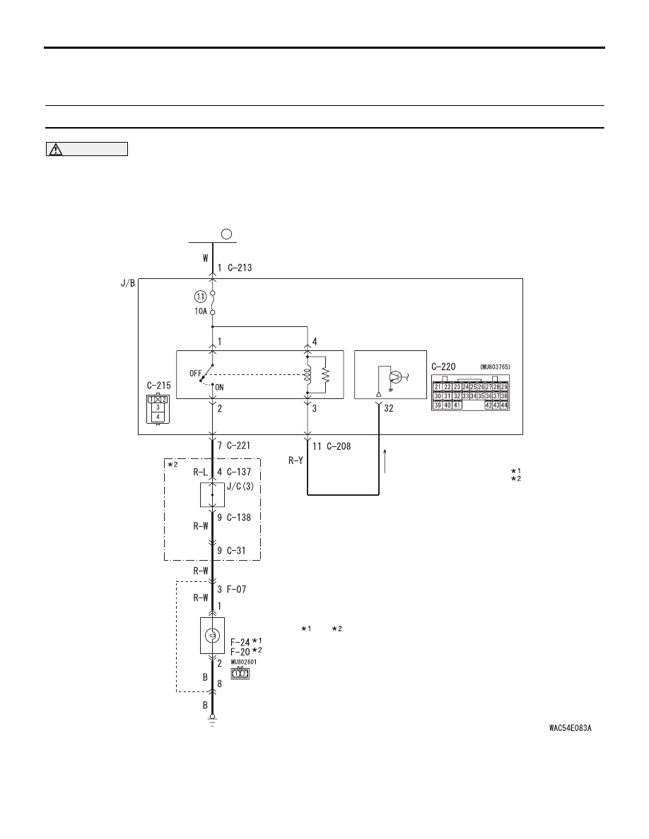
Rear Fog Lamp Circuit

ETACS-ECU

REAR 
FOG 
LAMP 
RELAY

FUSIBLE 
LINK

20

NOTE

: LHD
: RHD

REAR 
FOG LAMP (LH)    (RH)

Wire colour code 
B : Black     LG : Light green     
G : Green     L : Blue     
W : White     Y : Yellow     
SB : Sky blue BR : Brown     
O : Orange     GR : Grey     
R : Red     P : Pink     V : Violet     
PU : Purple     SI : Silver

REAR FOG LAMP

CHASSIS ELECTRICAL

54A-168

PROBABLE CAUSES

• Malfunction of the column switch

• Malfunction of the rear fog lamp relay

• Burned-out rear fog lamp bulb

• Malfunction of the ETACS-ECU

• Damaged harness wires and connectors

DIAGNOSIS PROCEDURE

STEP 1. Check that the rear fog lamp indicator 
operate.
Check that the rear fog lamp indicator illuminates.

Q: Does the rear fog lamp indicator illuminate?

YES : 

Go to Step 12.

NO : 

Go to Step 2.

STEP 2. Check that the tail/stop lamps and 
headlamps operate.
Check that the tail/stop lamps and headlamps illumi-
nate normally.

Q: Is the check result normal?

YES : 

Go to Step 3.

NO : 

Repair the tail/stop lamp(s) and 
headlamp(s). Refer to trouble symptom 
chart 

P.54A-109

.

STEP 3. M.U.T.-III diagnosis code.
When the ignition switch is turned to the "LOCK" 
(OFF) position, check that the ETACS-ECU does not 
set the diagnosis code.

Q: Is the diagnosis code set?

YES : 

Refer to diagnosis code chart 

P.54A-494

.

NO : 

Go to Step 4.

STEP 4. M.U.T.-III data list
Check the input signals below, which are related to 
the rear fog lamp.

• Turn the ignition switch to the "LOCK" (OFF) 

position.

• Turn the tail lamp switch to the ON position.

• Turn the rear fog lamp switch to the ON position.

OK: Normal conditions are displayed for all 
the items

Q: Are the check result normal?

YES <All the signals are received normally.> : 

Go 

to Step 5.

NO <The ignition switch (IG1) signal is not 
received.> : 

Refer to inspection procedure C-3 

"The ignition switch (IG1) signal is not 
received 

P.54A-533

."

NO <The rear fog lamp switch signal is not 
received.> : 

Refer to inspection procedure C-1 

"The column switch (lighting and wiper 
switch) signal is not received 

P.54A-523

."

STEP 5. Connector check: C-215 rear fog lamp 
relay connector

Q: Is the check result normal?

YES : 

Go to Step 6.

NO : 

Repair the defective connector.

STEP 6. Check the rear fog lamp relay.
Refer to 

P.54A-176

.

Q: Is the check result normal?

YES : 

Go to Step 7.

NO : 

Replace the rear fog lamp relay.

Item 
No.

Item name

Normal condition

30

Ignition switch(IG1)

OFF

71

Rear fog lamp

ON

AC509934

Connector: C-215 <LHD>

AP

Junction block

Junction block side

AC509936

Connector: C-215 <RHD>

AL

Junction block 
(Front view)

Junction block side

REAR FOG LAMP

CHASSIS ELECTRICAL

54A-169

STEP 7. Voltage measurement at the C-215 rear 
fog lamp relay connector.

(1) Remove the rear fog lamp relay, and measure at 

the junction block side.

(2) Check the voltage between the rear fog lamp 

relay connector and body earth.

• Voltage between C-215 rear fog lamp relay 

connector terminal No.1 and body earth

• Voltage between C-215 rear fog lamp relay 

connector terminal No.4 and body earth

OK: System voltage

Q: Is the check result normal?

YES : 

Go to Step 9.

NO : 

Go to Step 8.

STEP 8. Check the wiring harness between C-215 
rear fog lamp relay connector terminals Nos.1, 4 
and the fusible link (20).

NOTE: Prior to the wiring harness inspection, check 
junction block connector C-213, and repair if neces-
sary.

• Check the power supply line for open circuit and 

short circuit.

Q: Is the check result normal?

YES : 

Go to Step 11.

NO : 

Repair the wiring harness.

AC509934

Connector: C-215 <LHD>

AP

Junction block

Junction block side

AC509936

Connector: C-215 <RHD>

AL

Junction block 
(Front view)

Junction block side

AC310507 LU

Connector C-215 
(Junction block side)

AC509934

Connector: C-213, C-215 <LHD>

Junction 
block

AQ

Harness side

C-213

C-215

C-213

Junction block 
side

C-215

AC509936

Connectors: C-213, C-215 <RHD>

Harness side

C-213

C-215

C-213

AM

Junction block 

(Front view)

Junction block side

C-215

REAR FOG LAMP

CHASSIS ELECTRICAL

54A-170

STEP 9. Connector check: C-220 ETACS-ECU 
connector

Q: Is the check result normal?

YES : 

Go to Step 10.

NO : 

Repair the defective connector.

STEP 10. Check the wiring harness between C-
215 rear fog lamp relay connector terminal No.3 
and C-220 ETACS-ECU connector terminal No.32.

NOTE: Prior to the wiring harness inspection, check 
junction block connector C-208, and repair if neces-
sary.

• Check the output lines for open circuit.

Q: Is the check result normal?

YES : 

Go to Step 11.

NO : 

Repair the wiring harness.

AC509934

Connector: C-220 <LHD>

AM

Junction block

Harness side

AC509943

Connector: C-220 <RHD>

AD

Junction block
 (Rear view)

Harness side

AC509935AJ

Connectors: C-208, C-215, C-220 <LHD>

C-220

C-208

Harness side

C-220

C-215

Harness side

C-208

C-215

Junction block side

AC509936

Connectors: C-208, C-215 <RHD>

Harness side

C-208

C-215

BC

Junction block 

(Front view)

Junction block side

C-215

C-208

AC509943

Connector: C-220 <RHD>

AD

Junction block
 (Rear view)

Harness side


Content   ..  698  699  700  701   ..