Mitsubishi L200. Manual - part 605


  Index      Mitsubishi     Mitsubishi L200 - service repair manual 2012 year


Search            


Content   ..  603  604  605  606   ..


Mitsubishi L200. Manual - part 605


TROUBLESHOOTING

SUPPLEMENTAL RESTRAINT SYSTEM (SRS)

52B-91

DIAGNOSIS PROCEDURE

STEP 1. Check the diagnosis code by connecting 
a dummy resistor. (M.U.T.-III diagnosis code)
(1) Disconnect the negative battery terminal.

AC501889

AC511604

AD

Harness side 
connector 
(front view)

Connectors: D-23 <LHD>, D-15 <RHD>

D-15 (B)

Centre

pillar

D-23 (B)

AC300147AV

Seat belt 
pre-tensioner
connector

Flat-tipped 
screwdriver

Locking button

Harness side connector

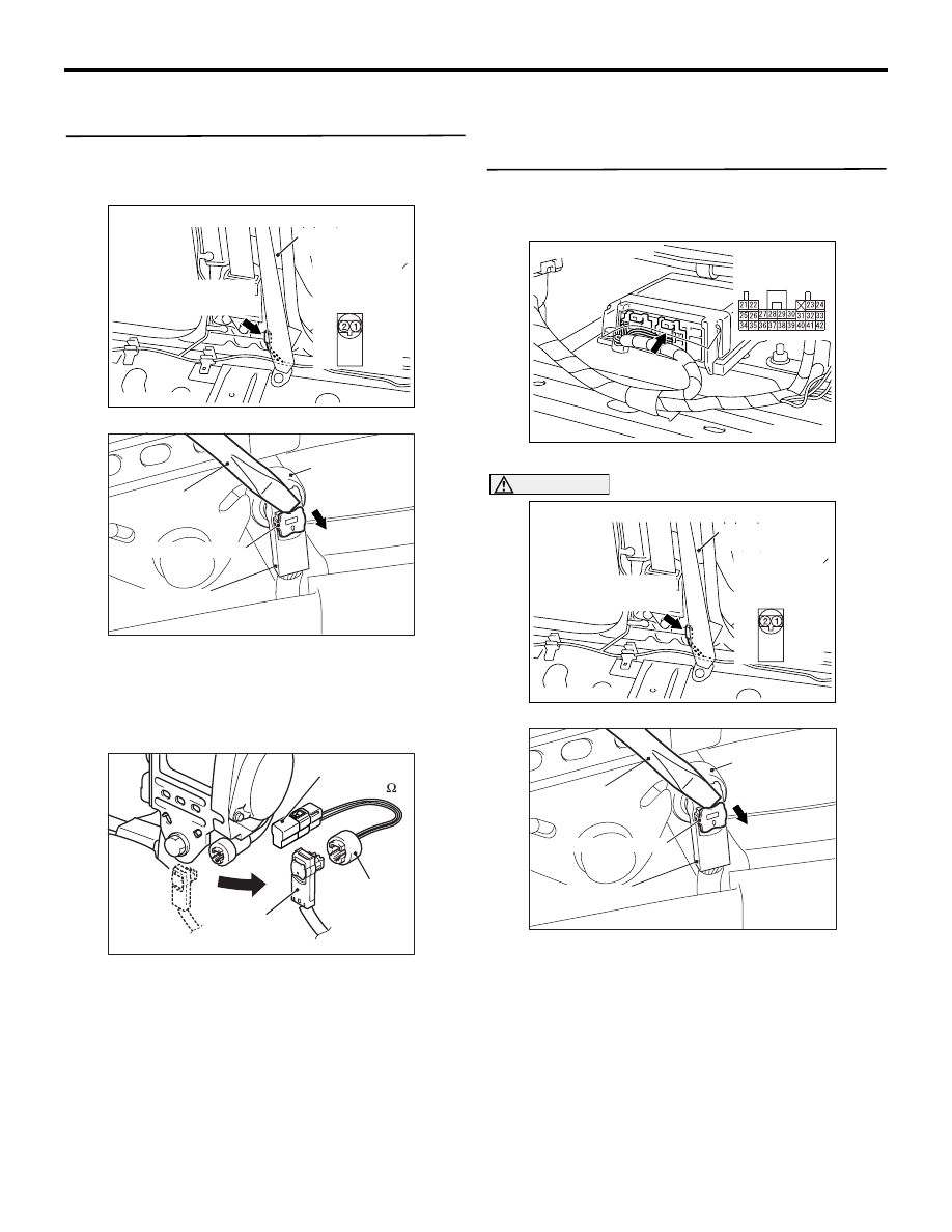
(2) Disconnect seat belt pre-tensioner (passenger's 

side) connector D-23 <LHD> or D-15 <RHD>. 
Use a flat-tipped screwdriver to pull out the 
locking button at the harness side connector, and 
then disconnect the connector.

AC501975

MB991865

(Dummy 

resistor : 3   )

MB991884 
(Resistor 
harness)

AF

Harness 
side connector

(3) Connect special tool dummy resistor (MB991865) 

to special tool resistor harness (MB991884).

(4) Connect special tool (MB991884) to the D-23 

<LHD> or D-15 <RHD> harness side connector.

(5) Connect the negative battery terminal.
(6) Erase diagnosis code memory, and then check 

the diagnosis code.

Q: Is diagnosis code B1612 set?

YES : 

Go to Step 2.

NO : 

Replace the seat belt with pre-tensioner 
(passenger's side) (Refer to 

P.52B-284

).

STEP 2. Voltage measurement at the SRS-ECU 
connector C-130.
(1) Disconnect the negative battery terminal.

AC501670

AC

C-130 (Y)

Connector: C-130

Harness side 
connector 
(rear view)

(2) Disconnect SRS-ECU connector C-130.

AC501889

AC511604

AD

Harness side 
connector 
(front view)

Connectors: D-23 <LHD>, D-15 <RHD>

D-15 (B)

Centre

pillar

D-23 (B)

AC300147AV

Seat belt 
pre-tensioner
connector

Flat-tipped 
screwdriver

Locking button

Harness side connector

DANGER

To prevents the seat belt pre-tensioner from 
deploying unintentionally, disconnect the 
seat belt pre-tensioner (passenger's side) 
connector D-23 <LHD> or D-15 <RHD> to 
short the squib circuit.

(3) Disconnect seat belt pre-tensioner (passenger's 

side) connector D-23 <LHD> or D-15 <RHD>. 
Use a flat-tipped screwdriver to pull out the 
locking button at the harness side connector, and 

TROUBLESHOOTING

SUPPLEMENTAL RESTRAINT SYSTEM (SRS)

52B-92

then disconnect the connector.

AC300994

AB

AE

A

A

C-130 Harness side
connector (front view)

Terminal

Cable tie

Short spring

4 mm or more

Section
A - A

CAUTION

Insert an insulator such as a cable tie to a depth 
of 4 mm or more, otherwise the short spring will 
not be released.
(4) Insert a cable tie [3 mm wide, 0.5 mm thick] 

between terminals 27, 28 and the short spring to 
release the short spring.

(5) Connect the negative battery terminal.

(6) Turn the ignition switch to the "ON" position,

AC501405

C-130 Harness side 
connector (rear view)

AC

CAUTION

Do not insert a test probe into the terminal from 
its front side directly as the connector contact 
pressure may be weakened.
(7) Voltage measurement between C-130 harness 

side connector terminals 27, 28 and body earth.

OK: 1 V or less

Q: Is the check result normal?

YES : 

Go to Step 3.

NO : 

Repair the harness wires between SRS-
ECU connector C-130 (terminal No.27 and 
28) and the seat belt pre-tensioner 
(passenger's side) connector D-23 <LHD> 
or D-15 <RHD> (terminal No.2 and 1)

STEP 3. Check whether the diagnosis code is 
reset.

Q: Is diagnosis code B1612 set?

YES : 

Replace the SRS-ECU (Refer to 

P.52B-

266

).

NO : 

An intermittent malfunction is suspected 
(Refer to GROUP 00, How to Cope with 
Intermittent Malfunction ).

TROUBLESHOOTING

SUPPLEMENTAL RESTRAINT SYSTEM (SRS)

52B-93

DIAGNOSIS CODE PROCEDURES 
<VEHICLES WITH SIDE-AIRBAG AND 
CURTAIN AIR BAG>

Code No.B1400: Driver's air bag module (squib) system (short-circuited between terminals of the 
squib circuit)

AC805793

Driver's Air Bag Module (Squib) Circuit

AIR BAG MODULE
(SQUIB)
(DRIVER'S SIDE)

CONNECTOR
LOCK SWITCH

CONNECTOR
LOCK SWITCH

CLOCK SPRING

SRS-ECU

CONNECTOR
LOCK SWITCH

NOTE

: CONNECTOR COUPLED: ON 
  CONNECTOR UNCOUPLED: OFF

Wire colour code
B : Black     LG : Light green     G : Green     L : Blue     W : White     Y : Yellow     SB : Sky blue
BR : Brown     O : Orange     GR : Grey     R : Red     P : Pink     V : Violet     PU : Purple

AB

OPERATION

• The SRS-ECU judges how severe a collision is 

by detecting signals from the front impact sensors 
and the front air bag analogue G-sensor. If the 
impact is over a predetermined level, the SRS-
ECU sends an ignition signal. At this time, if the 
front air bag safing G-sensor is on, the SRS air 
bag will inflate. 

• The ignition signal is input to the air bag module 

via the clock spring to inflate the air bag.

DIAGNOSIS CODE SET CONDITIONS
This diagnosis code is set if one driver's air bag 
squib wire shorted to the other.

PROBABLE CAUSES

• Improper engaged connector or defective short 

spring*

• Short circuit in the clock spring

• Short circuit between the driver's air bag module 

(squib) circuit terminals

• Damaged connector(s)

• Malfunction of the SRS-ECU

TROUBLESHOOTING

SUPPLEMENTAL RESTRAINT SYSTEM (SRS)

52B-94

NOTE: *: The squib circuit connectors integrate a 
"short" spring (which prevents the air bag from 
deploying unintentionally due to static electricity by 
shorting the positive wire to the earth wire in the 
squib circuit when the connectors are disconnected). 
Therefore, if connector C-154, C-303 or C-305 is 
damaged or improperly engaged, the short spring 
may not be released when the connector is con-
nected.

DIAGNOSIS PROCEDURE

STEP 1. M.U.T.-III diagnosis code.

Q: Is diagnosis code B1519 set?

YES : 

Go to Step 2.

NO : 

Go to Step 3.

STEP 2. Connector lock check: SRS-ECU 
connector C-154. (M.U.T.-III diagnosis code)
(1) Disconnect the negative battery terminal.

AC801404

AJ

Connector: C-154

C-154 (Y)

Harness side 
connector 
(rear view)

(2) Disconnect connectors C-154 and then 

reconnect them.

(3) Connect the negative battery terminal.
(4) Erase the diagnosis code memory, and check the 

diagnosis code.

Q: Is diagnosis code B1400 set?

YES : 

Go to Step 3.

NO : 

The procedure is complete. It is assumed 
that diagnosis code B1400 set as connector 
C-154 was engaged improperly.

STEP 3. Connector lock check: SRS-ECU 
connector C-154, clock spring connector C-305 
and driver’s air bag module connector C-303. 
(M.U.T.-III diagnosis code)
(1) Disconnect the negative battery terminal.

AC801404

AJ

Connector: C-154

C-154 (Y)

Harness side 
connector 
(rear view)

AC903858AE

Connectors: C-303, C-305 <LHD>

C-305 (Y)

Harness side 
connector 
(front view)

C-303

C-303

C-305

AC903869AE

Connectors: C-303, C-305 <RHD>

C-305 (Y)

Harness side 
connector 
(front view)

C-303

C-303

C-305

(2) Disconnect connectors C-154, C-305 and C-303, 

and then reconnect them.

(3) Connect the negative battery terminal.
(4) Erase the diagnosis code memory, and check the 

diagnosis code.

Q: Is diagnosis code B1400 set?

YES : 

Go to Step 4.

NO : 

The procedure is complete. It is assumed 
that diagnosis code B1400 set as connector 
C-154, C-305 or C-303 was engaged 
improperly.


Content   ..  603  604  605  606   ..