Mitsubishi L200. Manual - part 603


  Index      Mitsubishi     Mitsubishi L200 - service repair manual 2012 year


Search            


Content   ..  601  602  603  604   ..


Mitsubishi L200. Manual - part 603


TROUBLESHOOTING

SUPPLEMENTAL RESTRAINT SYSTEM (SRS)

52B-83

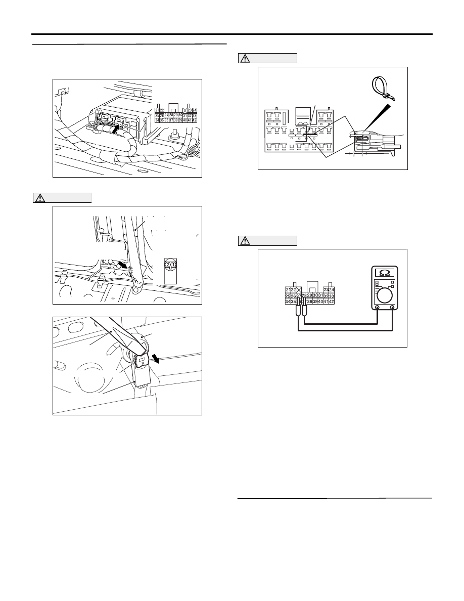
STEP 5. Resistance measurement at the SRS-
ECU connector C-130.
(1) Disconnect the negative battery terminal.

AC501670

AC

C-130 (Y)

Connector: C-130

Harness side 
connector 
(rear view)

(2) Disconnect SRS-ECU connector C-130.

AC501889

AC511604

AD

Harness side 
connector 
(front view)

Connectors: D-23 <LHD>, D-15 <RHD>

D-15 (B)

Centre

pillar

D-23 (B)

AC300147AV

Seat belt 
pre-tensioner
connector

Flat-tipped 
screwdriver

Locking button

Harness side connector

DANGER

To prevents the seat belt pre-tensioner from 
deploying unintentionally, disconnect the 
seat belt pre-tensioner (passenger's side) 
connector D-23 <LHD> or D-15 <RHD> to 
short the squib circuit.

(3) Disconnect seat belt pre-tensioner (passenger's 

side) connector D-23 <LHD> or D-15 <RHD>. 
Use a flat-tipped screwdriver to pull out the 
locking button at the harness side connector, and 

then disconnect the connector.

AC300994

AB

AE

A

A

C-130 Harness side
connector (front view)

Terminal

Cable tie

Short spring

4 mm or more

Section
A - A

CAUTION

Insert an insulator such as a cable tie to a depth 
of 4 mm or more, otherwise the short spring will 
not be released.
(4) Insert a cable tie [3 mm wide, 0.5 mm thick] 

between terminals 27, 28 and the short spring to 
release the short spring.

AC501402

AC501402

C-130 Harness side 
connector (rear view)
 

AD

CAUTION

Do not insert a test probe into the terminal from 
its front side directly as the connector contact 
pressure may be weakened.
(5) Resistance measurement between C-130 

harness side connector terminals 27 and 28.

OK: Open circuit.

Q: Is the check result normal?

YES : 

Go to Step 6 .

NO : 

Repair the harness wires between SRS-
ECU connector C-130 (terminal No.27 and 
28) and the seat belt pre-tensioner 
(passenger's side) connector D-23 <LHD> 
or D-15 <RHD> (terminal No.2 and 1)

STEP 6. Check whether the diagnosis code is 
reset.

Q: Is diagnosis code B1609 set?

TROUBLESHOOTING

SUPPLEMENTAL RESTRAINT SYSTEM (SRS)

52B-84

YES : 

Replace the SRS-ECU (Refer to 

P.52B-

266

).

NO : 

An intermittent malfunction is suspected 
(Refer to GROUP 00, How to Cope with 
Intermittent Malfunction ).

Code No.B1610: Seat belt pre-tensioner (passenger's side) (squib) system (open-circuited in the 
squib circuit)

AC805785

SRS-ECU

CONNECTOR
LOCK SWITCH

CONNECTOR
LOCK SWITCH

NOTE

: CONNECTOR COUPLED: ON 
  CONNECTOR UNCOUPLED: OFF

Wire colour code
B : Black     LG : Light green     G : Green     L : Blue     W : White     Y : Yellow     SB : Sky blue
BR : Brown     O : Orange     GR : Grey     R : Red     P : Pink     V : Violet     PU : Purple

AE

SEAT BELT 
PRE-TENSIONER 

CONNECTOR
LOCK SWITCH

<RHD>
<LHD>

Seat Belt Pre-tensioner (Passenger's Side)  (Squib)

OPERATION
The SRS-ECU judges how severe a collision is by 
detecting signals from the front impact sensors and 
the front air bag analogue G-sensor. If the impact is 
over a predetermined level, the SRS-ECU sends an 
ignition signal. At this time, if the front air bag safing 
G-sensor is on, the seat belt pre-tensioner will 
deploy. 

DIAGNOSIS CODE SET CONDITIONS
This diagnosis code is set if the seat belt pre-ten-
sioner (passenger's side) squib wire(s) are open-
circuited.

PROBABLE CAUSES

• Open circuit in the seat belt pre-tensioner (pas-

senger's side) (squib) circuit

• Improper connector contact

• Malfunction of the SRS-ECU

TROUBLESHOOTING

SUPPLEMENTAL RESTRAINT SYSTEM (SRS)

52B-85

DIAGNOSIS PROCEDURE

STEP 1. Check the diagnosis code by connecting 
a dummy resistor. (M.U.T.-III diagnosis code)
(1) Disconnect the negative battery terminal.

AC501889

AC511604

AD

Harness side 
connector 
(front view)

Connectors: D-23 <LHD>, D-15 <RHD>

D-15 (B)

Centre

pillar

D-23 (B)

AC300147AV

Seat belt 
pre-tensioner
connector

Flat-tipped 
screwdriver

Locking button

Harness side connector

(2) Disconnect seat belt pre-tensioner (passenger's 

side) connector D-23 <LHD> or D-15 <RHD>. 
Use a flat-tipped screwdriver to pull out the 
locking button at the harness side connector, and 
then disconnect the connector.

AC501975

MB991865

(Dummy 

resistor : 3   )

MB991884 
(Resistor 
harness)

AF

Harness 
side connector

(3) Connect special tool dummy resistor (MB991865) 

to special tool resistor harness (MB991884).

(4) Connect special tool (MB991884) to the D-23 

<LHD> or D-15 <RHD> harness side connector.

(5) Connect the negative battery terminal.
(6) Erase diagnosis code memory, and then check 

the diagnosis code.

Q: Is diagnosis code B1610 set?

YES : 

Go to Step 2.

NO : 

Replace the seat belt with pre-tensioner 
(passenger's side) (Refer to 

P.52B-284

). 

STEP 2. Resistance measurement between SRS-
ECU connector C-130 (terminal No.27 and 28) 
and the seat belt pre-tensioner (passenger's 
side) connector D-23 <LHD> or D-15 <RHD> 
(terminal No.2 and 1)
(1) Disconnect the negative battery terminal.

AC501670

AC

C-130 (Y)

Connector: C-130

Harness side 
connector 
(rear view)

(2) Disconnect SRS-ECU connector C-130.

AC501889

AC511604

AD

Harness side 
connector 
(front view)

Connectors: D-23 <LHD>, D-15 <RHD>

D-15 (B)

Centre

pillar

D-23 (B)

AC300147AV

Seat belt 
pre-tensioner
connector

Flat-tipped 
screwdriver

Locking button

Harness side connector

DANGER

To prevents the seat belt pre-tensioner from 
deploying unintentionally, disconnect the 
seat belt pre-tensioner (passenger's side) 
connector D-23 <LHD> or D-15 <RHD> to 
short the squib circuit.

(3) Disconnect seat belt pre-tensioner (passenger's 

side) connector D-23 <LHD> or D-15 <RHD>. 
Use a flat-tipped screwdriver to pull out the 

TROUBLESHOOTING

SUPPLEMENTAL RESTRAINT SYSTEM (SRS)

52B-86

locking button at the harness side connector, and 
then disconnect the connector.

AC300994

AB

AE

A

A

C-130 Harness side
connector (front view)

Terminal

Cable tie

Short spring

4 mm or more

Section
A - A

CAUTION

Insert an insulator such as a cable tie to a depth 
of 4 mm or more, otherwise the short spring will 
not be released.
(4) Insert a cable tie [3 mm wide, 0.5 mm thick] 

between terminals 27, 28 and the short spring to 
release the short spring.

AC201287CQ

H

arness side

connector

MB991884

(5) Connect D-23 <LHD> or D-15 <RHD> harness 

side connector to special tool resistor harness 

(MB991884).

AC501402 AE

C-130 
Harness side
connectors (rear view)

Special tool
MB991884

CAUTION

Do not insert a test probe into the terminal from 
its front side directly as the connector contact 
pressure may be weakened.
(6) Resistance measurement between the following 

terminals. 

• SRS-ECU connector C-130 terminal No.27 

and the special tool terminal No.1

• SRS-ECU connector C-130 terminal No.28 

and the special tool terminal No.2

OK: Continuity (Less than 2 

)

Q: Are the check results normal?

YES : 

Go to Step 3 .

NO : 

Repair the harness wires between SRS-
ECU connector C-130 (terminal No.27 and 
28) and the seat belt pre-tensioner 
(passenger's side) connector D-23 <LHD> 
or D-15 <RHD> (terminal No.2 and 1)

STEP 3. Check whether the diagnosis code is 
reset.

Q: Is diagnosis code B1610 set?

YES : 

Replace the SRS-ECU (Refer to 

P.52B-

266

).

NO : 

An intermittent malfunction is suspected 
(Refer to GROUP 00, How to Cope with 
Intermittent Malfunction ).


Content   ..  601  602  603  604   ..