Mitsubishi L200. Manual - part 547
AC903805AB
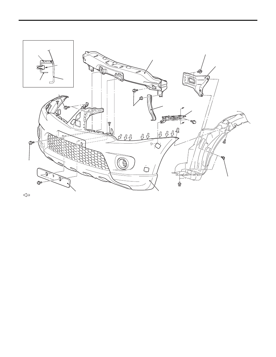
2
6
4
5
3
4.0 ± 2.0 N·m
4.0 ± 2.0 N·m
4.0 ± 2.0 N·m
9.5 ± 3.5 N·m
9.5 ± 3.5 N·m
1
: Claw positions
Section A – A
A
Claw
Screw
3
4
A
<Vehicles for Europe: Club and double cab>
Removal steps
•
Radiator grille (Refer to
.)
•
Front overfender (Refer to
1. Licence plate garnish
2. Front bumper side stay
•
Fog lamp connector connection
<vehicles with fog lamp>
3. Front bumper assembly
4. Front bumper support bracket
5. Front bumper stay
6. Front bumper reinforcement
FRONT BUMPER ASSEMBLY
EXTERIOR
51-4
Removal steps (Continued)