Mitsubishi L200. Manual - part 544
AC501256
A
B
C
E
E
G
A
B
C
D
F
G
A
B
C
D
D
F
F
G
E
AG
1
1
1
6
6
6
2
2
2
7
7
7
3
3
3
4
4
4
5
5
5
8
8
9
9
10
10
10
11
11
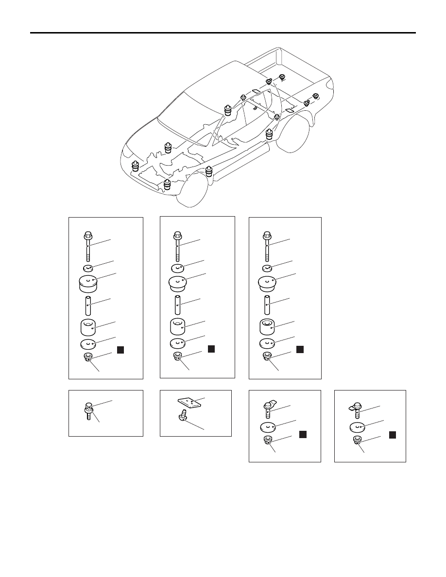
47 ± 7 N·m
47 ± 7 N·m
47 ± 7 N·m
45 ± 5 N·m
45 ± 5 N·m
63 ± 7 N·m
<Double cab>
N
N
N
N
N
Cab body mounting removal steps
1. Cab body mounting nut
2. Cab body mounting washer
3. Cab body mounting cushion
4. Cab body mounting spacer
5. Cab body mounting cushion
6. Cab body mounting washer
7. Cab body mounting bolt
<<A>>
•
Cab body
BODY MOUNTING
BODY
42-236
Rear body mounting removal
steps
8. Rear body mounting nut
9. Rear body mounting screw or bolt
10. Rear body mounting shim
Cab body mounting removal steps