Mitsubishi L200. Manual - part 542
AC303362AD
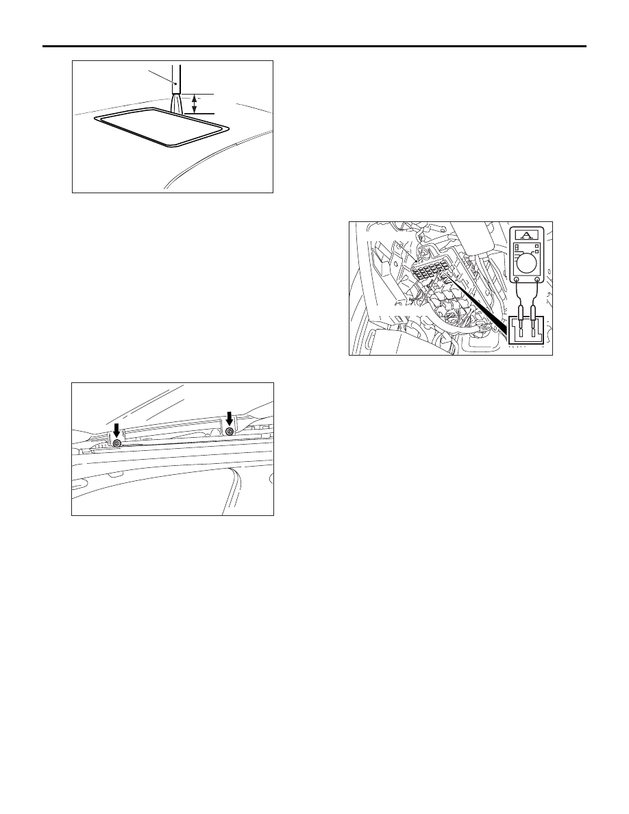
Hose
Approx.
30 cm
SUNROOF ASSEMBLY
BODY
42-228
3. Hold the end of the hose approx. 30 cm above the
roof and let the water run onto the weatherstrip for
5 minutes or more.
4. Check if any water leaks can be found in the
vehicle interior while watering. Even though there
are any water leaks around the sunroof lid glass, it
can be acceptable as long as water is caught in
the drip area.
SUNROOF FIT ADJUSTMENT
M1426001000434
1. Close the sunroof lid glass completely.
2. Open the sun shade completely.
AC506534 AB
3. Loosen the sunroof lid glass assembly mounting
screws as shown in the illustration. Adjust the
sunroof lid glass height by moving the glass
assembly along the guide oblong hole so that the
clearance between the glass and the vehicle body
is even.
4. After adjustment, check that the sunroof operates
smoothly.
SUNROOF OPERATION CHECK
M1426002600484
Check to see that the sunroof operates by pressing
the sunroof switch. Perform troubleshooting if opera-
tions malfunction. Refer to
SUNROOF SAFETY FUNCTION CHECK
M1426004400312
1. Close the sunroof lid glass by applying an
approximately 10 mm thickness wooden board
placed at a right angle to the sunroof lid glass.
2. Check that the sunroof motor assembly rotates
reversely to open the sunroof lid glass when the
sunroof lid glass pinches the wooden board. If
there is a problem, carry out troubleshooting.
Refer to
.
NOTE: When the safety mechanism has been
operated 5 or more times continuously, carry out
sunroof initialisation. Refer to
.
SUNROOF LID GLASS OPERATION
CURRENT CHECK
M1426003200542
AC507492 AC
ETACS-ECU
Sunroof fuse
1. Remove the sunroof fuse to check that it is
normal, and connect a circuit tester as shown.
2. Turn ON the sunroof switch, then measure the
operating current of the intermediary segment
except when operation is starting, the sunroof is
fully closed, the sunroof is fully opened and the
sunroof is tilted fully up.
Standard value: 3 A or less (at 20
°C)
3. Check the following areas if the operating current
of the sunroof lid glass is outside the standard
value:
• Improperly installed sunroof assembly, deforma-
tion or any foreign substances
• Improperly fastened drive cable
• Tilting of sunroof lid glass
SUNROOF INITIALISATION
M1426004600286
Perform the following initialisation when the anti-trap
function has been triggered 5 times or more, or the
sunroof motor assembly is removed.
1. Press the close/tilt-down switch to move the
sunroof lid glass to the fully-tilted-up position.
Each switch operation makes the sunroof lid glass
move by approximately 30 mm and stops it
automatically. Repeat the operation to move the
sunroof lid glass to the fully-tilted-up position.
2. Hold the close/tilt-down switch for 3 seconds.