Mitsubishi L200. Manual - part 533
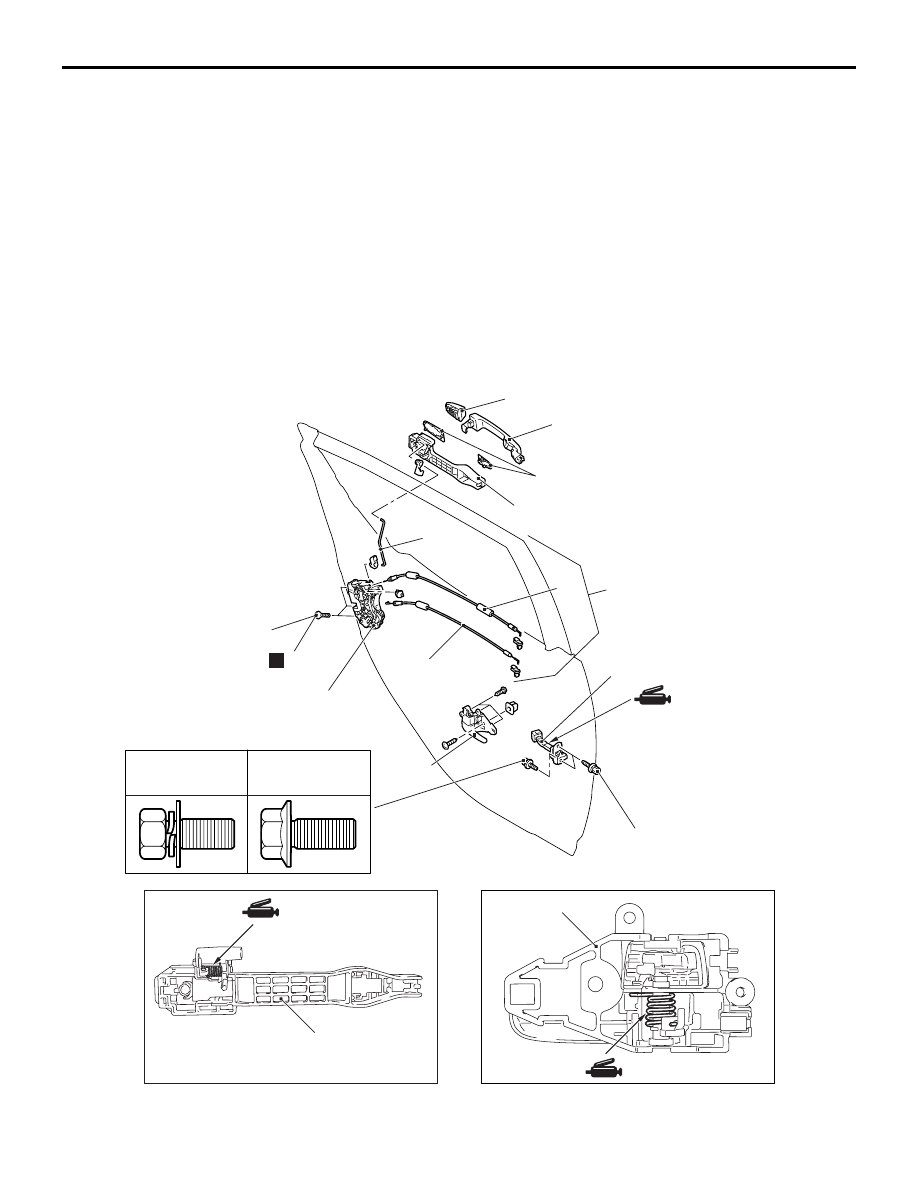
Door latch assembly removal
steps
•
Waterproof film and rear lower sash
(Refer to
.)
8.
Door latch and cable assembly
9.
Screw
10. Door latch assembly
11. Door inside lock cable
12. Door inside handle cable
13. Door outside handle rod
14. Door outside lock rod
15. Door panel bracket
Door check removal steps
•
.)
>>
A
<<
16. Door check
AC509778
5.0 ± 1.0 N·m
1
2
3
4
5
8
9
6
10
11
12
5.0 ± 1.0 N·m
7
N
AG
<Rear door>
31 ± 4 N·m
<Up to 2010 year
October>
24 ± 4 N·m
<From to 2010
year September>
AC509773
1
5
AB
DOOR
BODY
42-192