Mitsubishi L200. Manual - part 531
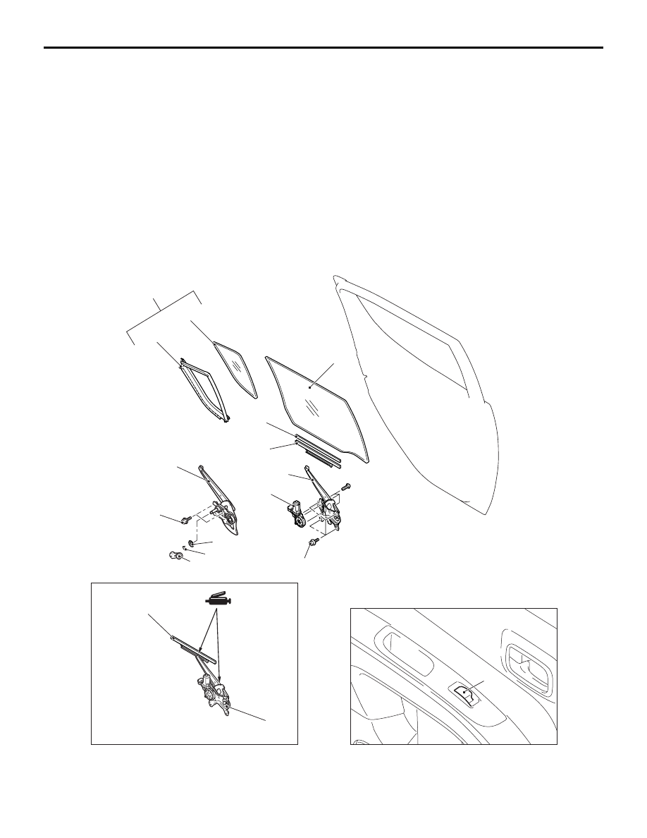
Door window glass assembly
removal steps
•
).
•
Beltline moulding, beltline
weatherstrip inner (Refer to
).
5.
Door window glass assembly
Door window regulator assembly
removal steps
>>
A
<<
•
Post-installation operation check
•
).
<<
B
>>
6.
Door window regulator assembly
7.
Power window motor <Vehicles
with power window>
AC509769
2
3
4
5
6
7
AD
<Vehicles with
power window>
<Vehicles without
power window>
<Rear door>
8
9
10
11
12
11
5.0 ± 1.0 N·m
5.0 ± 1.0 N·m
AC509770
1
11
7
AB
DOOR
BODY
42-184