Mitsubishi L200. Manual - part 474


  Index      Mitsubishi     Mitsubishi L200 - service repair manual 2012 year


Search            


Content   ..  472  473  474  475   ..


Mitsubishi L200. Manual - part 474


Parking brake front cable 
removal steps 

 Parking brake lever assembly 
(including parking brake switch) 
(Refer to 

P.36-6

.)

>>

A

<<

1.

Parking brake rear cable 
connection (parking brake lever 
side)

2.

Parking brake front cable
Parking brake rear cable removal 
steps 

Rear floor console cover assembly 
(Refer to GROUP 52A 

− Rear Floor 

Console Assembly .)

Loosen the adjusting nuts.

>>

A

<<

1.

Parking brake rear cable 
connection (parking brake lever 
side)

3.

Brake drum

4.

Parking brake rear cable 
connection (rear drum brake side)

5.

Parking brake rear cable

PARKING BRAKE CABLE <Vehicles with front separate seat>

PARKING BRAKES

36-9

INSTALLATION SERVICE POINT

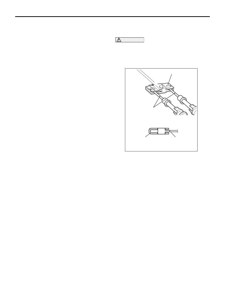
>>A<< PARKING BRAKE REAR CABLE INSTAL-
LATION

CAUTION

Check that the equaliser and the parking brake 
rear cable are connected correctly. If the parking 
brake is applied with the equaliser and the park-
ing brake rear cable connected improperly, the 
equaliser may be damaged.

AC903102 AB

Equalizer

Equalizer

Parking brake 
rear cable

Parking brake 
rear cable

A

A

Section A - A

Connect the parking brake rear cable to the equaliser 
as shown in the figure.

PARKING BRAKE REAR CABLE AND LEVER ASSEMBLY <Vehicles with front bench seat>

PARKING BRAKES

36-10

PARKING BRAKE REAR CABLE AND LEVER ASSEMBLY 

<Vehicles with front bench seat>

REMOVAL AND INSTALLATION

M1361003100053

Post-installation Operation
Parking brake pull rod stroke adjustment (Refer to 

P.36-4

).

AC506404AC

1

2

3

3

4

4

5

5

8

9

6

7

10

13

13

11

12

14

12

:Moving parts of lever assembly

Removal steps 

1.

Return spring

2.

Parking brake front cable 
connection (lever side)

3.

Adjusting nut

4.

Pin

5.

Adjusting nut

6.

Split pin

7.

Plain washer

8.

Spacer

9.

Clevis pin

10. Lever assembly
11. Brake drum
12. Parking brake rear cable 

connection (rear drum brake side)

13. Clip
14. Parking brake rear cable 

assembly

Removal steps (Continued)

37-1

GROUP 37

POWER STEERING

CONTENTS

GENERAL INFORMATION . . . . . . . .

37-2

SERVICE SPECIFICATION(S)  . . . . .

37-4

LUBRICANT(S)  . . . . . . . . . . . . . . . . .

37-5

SEALANT(S) AND ADHESIVE(S) . . .

37-5

SPECIAL TOOL(S)  . . . . . . . . . . . . . .

37-6

ON-VEHICLE SERVICE. . . . . . . . . . .

37-8

STEERING WHEEL FREE PLAY CHECK . 

37-8

STEERING ANGLE CHECK . . . . . . . . . . . . 

37-8

BALL JOINT DUST COVER INSPECTION  

37-9

TIE ROD END BALL JOINT STARTING TORQUE 
CHECK . . . . . . . . . . . . . . . . . . . . . . . . . . . . 

37-9

STATIONARY STEERING EFFORT CHECK


 . . . . . . . . . . . . . . . . . . . . . . . . . . . . . . . . . . . . . .

37-10

STEERING WHEEL RETURN TO CENTER CHECK


 . . . . . . . . . . . . . . . . . . . . . . . . . . . . . . . . . . . . . .

37-10

DRIVE-BELT TENSION CHECK  . . . . . . . . 

37-10

FLUID LEVEL CHECK  . . . . . . . . . . . . . . . . 

37-10

FLUID REPLACEMENT . . . . . . . . . . . . . . . 

37-11

POWER STEERING SYSTEM AIR BLEEDING


 . . . . . . . . . . . . . . . . . . . . . . . . . . . . . . . . . . . . . .

37-11

OIL PUMP PRESSURE TEST  . . . . . . . . . . 

37-12

POWER STEERING FLUID PRESSURE SWITCH 
CHECK . . . . . . . . . . . . . . . . . . . . . . . . . . . . 

37-13

STEERING COLUMN SHAFT ASSEMBLY SHOCK 
ABSORBING MECHANISM CHECK  . . . . . 

37-13

STEERING WHEEL . . . . . . . . . . . . . .

37-15

STEERING REMOVAL AND INSTALLATION


. . . . . . . . . . . . . . . . . . . . . . . . . . . . . . . . . . . . . . 

37-15

STEERING COLUMN SHAFT ASSEMBLY


 . . . . . . . . . . . . . . . . . . . . . . . . . . . . . . . . .

37-18

STEERING COLUMN SHAFT ASSEMBLY REMOVAL 
AND INSTALLATION  . . . . . . . . . . . . . . . . . 

37-18

STEERING COLUMN SHAFT ASSEMBLY 
DISASSEMBLY AND REASSEMBLY . . . . . 

37-20

POWER STEERING GEAR BOX AND 
LINKAGE  . . . . . . . . . . . . . . . . . . . . . .

37-22

POWER STEERING GEAR BOX AND LINKAGE 
REMOVAL AND INSTALLATION  . . . . . . . . 

37-22

INSPECTION. . . . . . . . . . . . . . . . . . . . . . . . 

37-25

POWER STEERING GEAR BOX AND LINKAGE 
DISASSEMBLY AND REASSEMBLY . . . . . 

37-26

POWER STEERING OIL PUMP ASSEMBLY


 . . . . . . . . . . . . . . . . . . . . . . . . . . . . . . . . .

37-36

POWER STEERING OIL PUMP ASSEMBLY 
REMOVAL AND INSTALLATION  . . . . . . . . 

37-36

POWER STEERING OIL PUMP ASSEMBLY 
INSPECTION. . . . . . . . . . . . . . . . . . . . . . . . 

37-37

POWER STEERING OIL PUMP ASSEMBLY 
DISASSEMBLY AND REASSEMBLY . . . . . 

37-38

POWER STEERING OIL PUMP ASSEMBLY 
INSPECTION (DISASSEMBLY AND REASSEMBLY)


. . . . . . . . . . . . . . . . . . . . . . . . . . . . . . . . . . . . . . 

37-39

POWER STEERING HOSES  . . . . . . .

37-40

POWER STEERING HOSES REMOVAL AND 
INSTALLATION . . . . . . . . . . . . . . . . . . . . . . 

37-40

GENERAL INFORMATION

POWER STEERING

37-2

GENERAL INFORMATION

M1372000101846

FEATURES

Power steering has been adopted in all vehicles to 
make the steering system easier to handle.

• A 4-spoke steering wheel is used.

• A 3-spoke steering wheel is used. <Option>

• A steering column has a shock absorbing mecha-

nism and a tilt steering mechanism.

• A rack and pinion steering gear is used for steer-

ing that feels more direct and for ample handling 
performance. 

• The steering angle has been enlarged to reduce 

the minimum turning radius.

• An oil pump responsive to engine rpm is used for 

stable steering at high speed. 

• The separate plastic resin oil reservoir is used to 

reduce weight and to make the fluid level check-
ing easier. 

• The flexible tube has been adopted for the pres-

sure hose and the hose length has been opti-
mised to reduce noise and vibration.

CONSTRUCTION DIAGRAM

2WD (Except High rider)-LHD

AC702428 AD

Steering wheel assembly

Steering column
shaft assembly

Steering column
support bracket

Suspension
crossmember

Steering gear box
assembly

Oil pump
assembly

Pressure
hose assembly

Suction
hose

Oil reservoir

Return
hose


Content   ..  472  473  474  475   ..