Mitsubishi L200. Manual - part 402
SPECIAL TOOLS
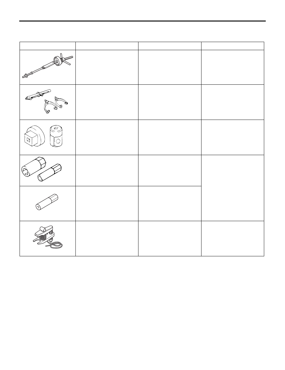
FRONT SUSPENSION
33-4
SPECIAL TOOLS
M1332000601063
Tool
Number
Name
Use
MB991783
MB992058
Coil spring compressor
Compression of front
suspension coil spring
<2WD (except High
rider)>
MB991237
A
B
A: MB991237
B: MB991238
A: Spring compressor
body
B: Arm set, large
Compression of front
suspension coil spring
<2WD (High rider), 4WD>
MB990326
MB990326
Preload socket
Ball joint starting torque
check
MB991680
A
B
MB991680
A: MB991681
Wrench and socket set
A: Wrench
Shock absorber assembly
disassembly and
reassembly
MB992047
MB992047
Socket
MB992011
MB992011
Ball joint remover
Upper arm and lower arm
ball joint disconnection