Mitsubishi L200. Manual - part 342


  Index      Mitsubishi     Mitsubishi L200 - service repair manual 2012 year


Search            


Content   ..  340  341  342  343   ..


Mitsubishi L200. Manual - part 342


TRANSFER

AUTOMATIC TRANSMISSION OVERHAUL <V4A5>

23C-77

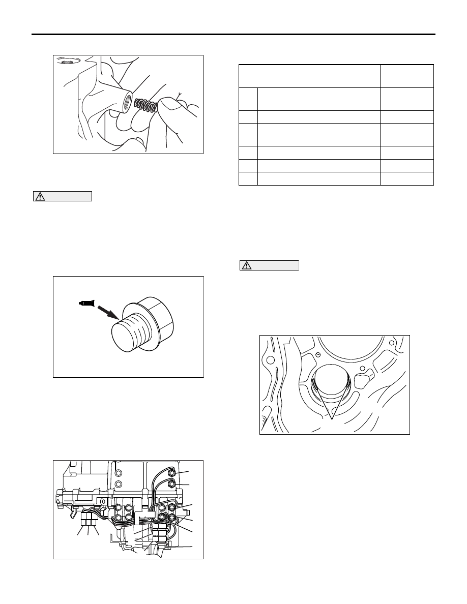
>>W<< SPRING INSTALLATION

AK403513

Install the spring with its tapered end toward the ball.

>>X<< PLUG INSTALLATION

CAUTION

• Completely degrease the FIPG-applied sur-

face so that water and oil including the old 
sealant cannot adhere to the surface coated 
with the sealant. Never touch the degreased 
surface by hand.

AK403514AB

Make sure the starting point and the ending 
point are about the middle between the bolts.

Apply the sealant to the threads.

Specified sealant:
 3M

 ATD Part No. 8672 or equivalent

NOTE: The new plug is percolated with sealant, so 
sealant does not need to be applied.

>>Y<< DETECTION SWITCH INSTALLATION

AK503496

A

B

C

D

E

F

AB

4

6

3

5

1

2

Install with care. Do not make mistake when locating 
each switch.

Detection switch name

Connector 
No. / Color

A

Center differential lock 
detection switch

1 / Brown

B

2WD/4WD detection switch

2 / Black

C

Center differential lock 
operation detection switch

4 / Blown

D

4WD operation detection switch 6 / Black

E

High/low detection switch

3 / white

F

4LLc detection switch

5 / White

ADJUSTMENT OF TRANSFER

M1233030900060

SPACER SELECTION FOR ADJUST-
MENT OF COUNTERSHAFT GEAR END 
PLAY

<Measurement using a solder>

CAUTION

• If soft solder is not available, select the 

spacer in accordance with Plastigage method.

• If the spacer appropriate for the standard 

value cannot be selected using soft solder, 
select the spacer in accordance with Plasti-
gage method.

AK403499AB

Solder

1. Put solders (1.0 mm diameter, about 10 mm long) 

in the illustrated positions of the transfer case 
housing.

2. Install the countershaft gear into the transfer case.
3. Install the transfer case plate and tighten the bolts 

to the specified torque of 35 

± 6 N⋅m.

4. Remove the transfer case plate and the 

countershaft gear, and then take out crushed 
solders.

5. If the solders have not crushed, use thicker 

solders (1.6 mm diameter, about 10 mm long) and 
repeat steps 2 to 4.

AK305233

TRANSFER

AUTOMATIC TRANSMISSION OVERHAUL <V4A5>

23C-78

6. Measure the thickness of the crushed solder with 

a micrometer and select a spacer that will provide 
the standard value.

Spacer thickness: (T 

 0) to (T  0.15)

T: The crushed solder thickness
Standard value: 0 

 0.15 mm

(For countershaft gear end play)

<Measurement using Plastigage>

AK403499AC

Plastigage

1. Put plastigage (about 10 mm long) in the 

illustrated positions of the transfer case housing.

2. Install the adjusting spacer having the minimum 

thickness.

3. Install the countershaft gear into the transfer case.
4. Install the transfer case plate and tighten the bolts 

to the specified torque of 35 

± 6 N⋅m.

5. Remove the transfer case plate and the 

countershaft gear, and then take out crushed 
solders.

6. If the Plastigages have not crushed, replace the 

spacer with a thicker one and repeat steps 3 to 5.

AK402081

Plastigage

Spacer

AB

7. Measure the width of the crushed Plastigage at its 

widest part using a scale printed on the Plastigage 
package.

Standard value: 0 

 0.15 mm

(For countershaft gear end play)

INSPECTION

M1233013400114

<Easy select 4WD>

4WD OPERATION DETECTION SWITCH

AK500505

Check for the continuity between the connector ter-
minals.

Switch 
condition

Connector 
terminals

Continuity

Switch end 
pressed

− 2

Conductive

Switch end 
released

− 2

Open

HIGH/LOW DETECTION SWITCH

AK500510

TRANSFER

AUTOMATIC TRANSMISSION OVERHAUL <V4A5>

23C-79

Check for the continuity between the connector ter-
minals.

Switch 
condition

Connector 
terminals

Continuity

Switch end 
pressed

− 2

Open

Switch end 
released

− 2

Conductive

LOW DETECTION SWITCH

AK500511

Check for the continuity between the connector ter-
minals.

Switch 
condition

Connector 
terminals

Continuity

Switch end 
pressed

− 2

Open

Switch end 
released

− 2

Conductive

<Super select 4WD>

CENTER DIFFERENTIAL LOCK DETECTION 
SWITCH, 2WD/4WD DETECTION SWITCH, 
CENTER DIFFERENTIAL LOCK OPERATION 
DETECTION SWITCH, 4WD OPERATION DETEC-
TION SWITCH, HIGH/LOW DETECTION SWITCH

AK503422

Check for the continuity between the connector ter-
minals.

Switch 
condition

Connector 
terminals

Continuity

Switch end 
pressed

− Body earth

Open

Switch end 
released

− Body earth

Conductive

4LLc DETECTION SWITCH

AK503422

Check for the continuity between the connector ter-
minals.

Switch 
condition

Connector 
terminals

Continuity

Switch end 
pressed

− Body earth

Conductive

Switch end 
released

− Body earth

Open

TRANSFER CASE PLATE

AUTOMATIC TRANSMISSION OVERHAUL <V4A5>

23C-80

TRANSFER CASE PLATE

DISASSEMBLY AND REASSEMBLY

M1233024200222

AK700641

Apply automatic
transmission fluid
to all moving parts
before installation.

4

5

6

1

2

AB

19 ± 3 N·m

3

Disassembly steps 

>>

B

<< 1.

Bolt

2.

Bearing retainer

3.

Transfer input gear

>>

A

<< 4.

Oil seal

5.

Baffle plate

6.

Transfer case plate

REASSEMBLY SERVICE POINT

>>A<< OIL SEAL INSTALLATION
1. Use socket wrench to install the oil seal.

Specified lubricant:
Mitsubishi Part No. 0101011 or equivalent

AKX00216

MB990938

MB990933

AD

2. Use special tools to install the oil seal.

• Installer bar (MB990938)

• Installer adapter (MB990933)

>>B<< BOLT INSTALLATION


Content   ..  340  341  342  343   ..