Mitsubishi L200. Manual - part 223


  Index      Mitsubishi     Mitsubishi L200 - service repair manual 2012 year


Search            


Content   ..  221  222  223  224   ..


Mitsubishi L200. Manual - part 223


GLOW SYSTEM

ENGINE ELECTRICAL

16-22

ON-VEHICLE SERVICE

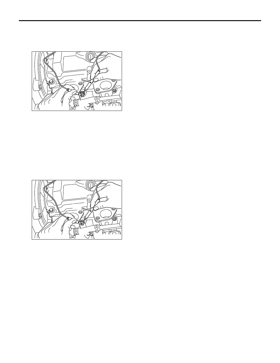
GLOW PLUG CHECK <EURO5>

M1164003400305

AK403892 AC

( - )

( + )

1. Disconnect the glow plug connector.
2. Measure the resistance between the glow plug 

terminal and the body, or the glow plug terminal 
and the cylinder head.

Standard value: 0.6 

 1.4  (at 20°C)

SELF-REGULATING GLOW SYSTEM CHECK <EXCEPT EURO5>

M1164001000260

SELF-REGULATING GLOW SYSTEM CHECK
1. Check that the battery voltage is 11 

− 13 V.

2. Check that the engine coolant temperature is 

40

°C or less.

NOTE: If the engine coolant temperature is too 
high, disconnect the engine coolant temperature 
sensor connector.

AK403875 AC

( - )

( + )

3. Measure the resistance between the glow plug 

plate and the glow plug body (earth).

Standard value: 0.15 

 0.25  (at 20°C)

NOTE: The resistance value is the parallel resist-
ance value for the four glow plugs.

4. Connect a voltmeter between the glow plug plate 

and the glow plug body (earth).

5. Measure the voltage immediately after the ignition 

switch is turned to ON (without starting the 
engine).

Standard value: 9 

 11 V (Drops to 0 V after 4 

 8 seconds have passed)

In addition, check to be sure that the glow indicator 
lamp (red) illuminates immediately after the ignition 
switch is turned to ON.

NOTE: The time during which the voltage appears 
(energizing time) will depend on the engine cool-
ant temperature.

6. Measure the voltage while the engine is cranking.

Standard value: 6 V or more

7. Start the engine and measure the voltage while 

the engine is warming up.
However, if the engine coolant temperature rises 
above 60

°C or when 180 seconds have passed 

since the engine was started, the voltage will 
always return to 0 V (Refer to the Glow Plug 
Energization Timing Chart).

Standard value: 12 

 15 V

GLOW SYSTEM

ENGINE ELECTRICAL

16-23

Glow Plug Energization Timing Chart <Reference>

AK403877

T1: Glow lamp

T2: Glow plug relay drive time after ignition switch is turned ON

T3: Glow plug relay drive time after engine starts (after glow)

START

Ignition
switch

Glow
lamp

Glow plug
relay

Crank angle
sensor

NOTE
After glow time T3 becomes longer as the engine coolant temperature drops

ON

OFF

ON

OFF

Idle

0 r/min

ON

OFF

AG

T1

T2

T3

CHECK AT THE ECU TERMINALS <EURO5>

M1164003600246

Refer to GROUP 13A 

− Troubleshooting − Check at 

the engine-ECU terminals .

CHECK AT THE ECU TERMINALS <EXCEPT EURO5>

M1164003600257

Refer to  GROUP 13A 

− Troubleshooting − Check at 

the engine-ECU terminals. 

GLOW PLUG RELAY CHECK <EXCEPT EURO5>

M1164003300160

AK403878AB

Glow plug relay

1. Disconnect the glow plug relay connector.
2. Measure resistance between terminal C and 

terminal E.

Standard value: 18 

 22  (at 20°C)

3. Use jumper cables to connect terminal C of the 

glow plug relay to the battery (+) terminal and 
terminal E to the battery (

−) terminal.

GLOW SYSTEM

ENGINE ELECTRICAL

16-24

CAUTION

1. Always be sure to disconnect the harnesses 

connected to glow plug relay terminals B and 
G before using the jumper cable.

2. The terminals of the disconnected harnesses 

must not be shorted to earth.

3. When connecting the jumper cable, be very 

careful not to make a mistake in connecting 
the terminal, as this will cause damage to the 
relay.

AK403881

B

C E

G

C

E

AB

G terminal

B terminal

4. Check the continuity between glow plug relay 

terminals B and G while disconnecting and 
connecting the jumper cable at the battery (+) 
terminal.

Jumper cable at battery (+) 
terminal

Continuity between 
terminals B 

− G

Connected

Continuity (0.01 

Ω or less)

Disconnected

No continuity (infinite 
resistance)

GLOW PLUG CHECK <EXCEPT EURO5>

M1164003400316

AK403892 AC

( - )

( + )

1. Remove the glow plug plate.
2. Measure the resistance between the glow plug 

terminals and the body.

Standard value: 0.6 

 1.0  (at 20°C)

ENGINE COOLANT TEMPERATURE 
SENSOR CHECK <EXCEPT EURO5>

M1164003500067

Refer to  GROUP 13A 

− On-vehicle service − Engine 

coolant temperature sensor check. 

GLOW SYSTEM

ENGINE ELECTRICAL

16-25

GLOW PLUG

REMOVAL AND INSTALLATION

M1164001800512

Pre-removal Operation
• Throttle Body Assembly Removal (Refer to GROUP 13A 

− Throttle Body ).

• EGR Valve and EGR Valve Pipe Removal (Refer to 

GROUP 17 

− EGR Valve and EGR Cooler ).

Post-installation Operation
• EGR Valve and EGR Valve Pipe Installation (Refer to 

GROUP 17 

− EGR Valve and EGR Cooler ).

• Throttle Body Assembly Installation (Refer to GROUP 

13A 

− Throttle Body ).

AC503049AE

5.0 ± 1.0 N·m

1.8 ± 0.2 N·m

17 ± 2 N·m

1

2

Removal steps 

1.

Glow plug connecting plate 
<Except Euro5>

2.

Glow plug

GLOW PLUG RELAY <Except Euro5>

REMOVAL AND INSTALLATION

M1164002400023

AC807146

1

2

3

9.0 ± 1.0 N·m

5.0 ± 1.0 N·m

9.0 ± 1.0 N·m

AB


Content   ..  221  222  223  224   ..