Mitsubishi L200. Manual - part 222


  Index      Mitsubishi     Mitsubishi L200 - service repair manual 2012 year


Search            


Content   ..  220  221  222  223   ..


Mitsubishi L200. Manual - part 222


GLOW SYSTEM

ENGINE ELECTRICAL

16-18

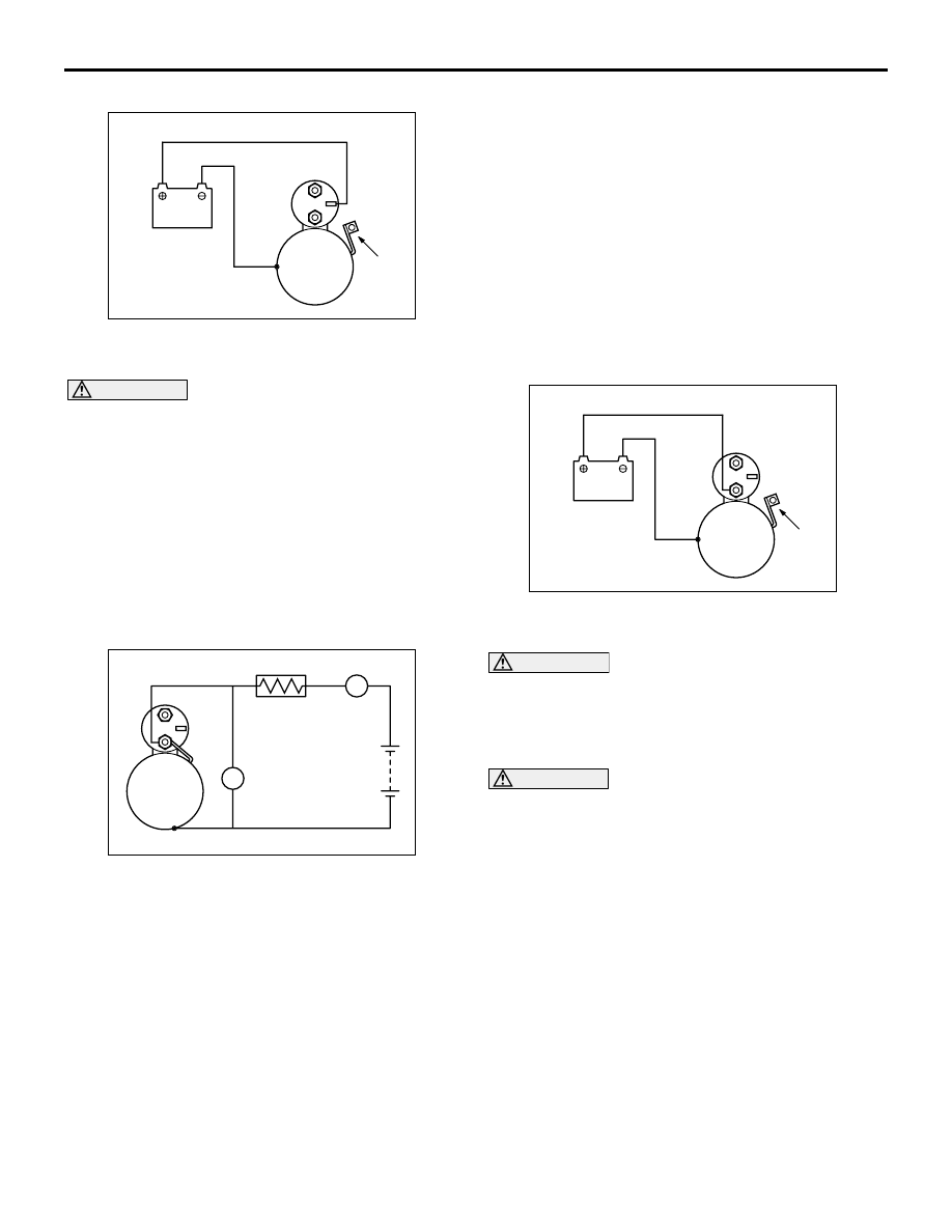
MAGNETIC SWITCH HOLD-IN TEST

AK403869

B

M

S

Battery

Starter 
motor

Wire

AB

1. Disconnect the field coil wire from the M-terminal 

of the magnetic switch.

CAUTION

This test must be performed quickly (in less than 
10 seconds) to prevent the coil from burning.
2. Connect a 12-volt battery between the S-terminal 

and body.

3. Manually pull out the pinion as far as the pinion 

stopper position.

4. If the pinion remains out, everything is in order. If 

the pinion moves in, the hold-in circuit is open. 
Replace the magnetic switch.

FREE RUNNING TEST

AK403870

B

M

S

A

V

Ammeter

Carbon-pile
rheostat

Battery

Starter
motor

Voltmeter

AB

1. Connect a test ammeter (150-ampere scale or 

more) and carbon pile rheostat in series between 
the positive battery terminal and starter motor 
terminal.

2. Connect a voltmeter (15-volt scale) across the 

starter motor.

3. Rotate the rheostat to full-resistance position.
4. Connect the battery cable from the negative 

battery terminal to the starter motor body.

5. Adjust the rheostat until the battery positive 

voltage shown on the voltmeter is 11 V.

6. Confirm that the maximum amperage is within the 

specifications and that the starter motor turns 
smoothly and freely.

Current: Maximum 130 A

MAGNETIC SWITCH RETURN TEST

AK403871

B

S

M

Battery

Starter 
motor

Wire

AB

1. Disconnect the field coil wire from the M-terminal 

of the magnetic switch.

CAUTION

This test must be performed quickly (in less than 
10 seconds) to prevent the coil from burning.
2. Connect a 12-volt battery between the M-terminal 

and body.

WARNING

Be careful not to get your fingers caught 
when pulling out the pinion.

3. Pull the pinion out and release. If the pinion 

quickly returns to its original position, everything is 
operating properly. If it doesn't, replace the 
magnetic switch.

GLOW SYSTEM

GENERAL INFORMATION

M1164000100178

GLOW SYSTEM <EURO5>

GLOW CONTROL
The glow control unit of the glow system employs the 
method of energizing the glow plug of each cylinder 
respectively.

The glow control unit carries out the duty control to 
the energization of the glow plug, in accordance with 
the signal from the engine-ECU.This achieves the 
optimum voltage of the glow plug in accordance with 
the engine conditions at the after glow to stabilize the 
combustion. Also the combustion noise or hydrocar-
bon (HC) emissions are reduced.

GLOW SYSTEM

ENGINE ELECTRICAL

16-19

System Configuration Diagram

AKB00122 AB

Power
MOSFET

Glow plug
control circuit

Glow control unit

Battery

Engine coolant
temperature sensor

Glow indicator
lamp

Combination 
meter

Engine-ECU

Crank angle sensor

Ignition switch-IG

Ignition switch-ST

Intake air temperature 
sensor

Control
signal

Diagnosis
signal

Manifold absolute
pressure sensor

Glow plug

Engine control relay

The engine-ECU determines the glow start, the glow 
time and the energization duty cycle of the glow plug. 
The engine-ECU outputs the PWM signal of the glow 
operation request to the glow control unit when the 
following conditions are satisfied.

Before starting (Pre-glow control)

• Ignition switch: ON

• Engine coolant temperature is 60°C or less.

Under the conditions of the engine not starting, the 
maximum energization time of the glow plug (duty of 
100%) is 20 seconds.

While running a cold engine (After-glow control)

• Ignition switch: ON

• Engine coolant temperature is 70°C or less.

• Engine speed is 350 r/min or more.

NOTE: The glow duty is determined in accordance 
with the engine coolant temperature and the intake 
air temperature (at the air flow sensor).
The maximum energization time of the glow plug is 
300 seconds.

Glow Indicator Lamp Control
When the engine coolant temperature is below a pre-
determined level, engine-ECU illuminates the glow 
indicator lamp. This causes the glow indicator lamp 
to illuminate, in order to inform the driver of the timing 
for starting the engine.

GLOW CONTROL UNIT

AKB00123

The glow control unit is installed to the fuel filter pro-
tector. The engine-ECU supplies the power to the 
control part of the glow control unit when the ignition 
switch is turned ON. The energization to the glow 
plug from the battery is controlled by installing the 
power-MOSFET (Metal Oxide Semiconductor Field 

GLOW SYSTEM

ENGINE ELECTRICAL

16-20

Effect Transistor) to the glow control unit for each cyl-
inder. When receiving the signal from the engine-
ECU through the control signal wire, the glow control 
unit controls the Power-MOSFET, based on the sig-
nal duty, to control the voltage for each glow plug. If 
detecting the open or short circuit of the glow plug, or 
communication failures to the engine-ECU, the glow 
control unit sends the malfunction signal to the 
engine-ECU through the diagnosis signal wire.

GLOW PLUG

AK802950 AB

Ceramic heating element

The glow plug is installed to each cylinder of the cyl-
inder head. The glow plug performs preheating of the 
combustion chamber with the ceramic heating ele-
ment on the acral part. The heating temperature of 
the glow plug is changed by adjusting the voltage 
applied to the glow plug through the duty control of 
the glow control unit.

AK802953AB

0

30

Energization time (s)

5

Driving current (A)

Heated portion temperature (˚C)

When 11 V is applied

When 11 V is applied

1000

500

The self control resistance is built in the ceramic 
heating element of the glow plug. When the current 
is going through the glow plug, the heating element 
heats up and the self control resistance increases, 
too.This gradually decreases the current going 
through the heating element to restrict the amount of 
heating the glow plug.

SELF-REGULATING GLOW SYSTEM 
<EXCEPT EURO 5>

The self-regulating glow system enables the vehicle 
to start ideally at low temperature by preheating the 
glow plug at super speed. When the ignition switch is 
turned to the ON position, the engine-ECU supplies 
electric currents and controls the glow lamp illumina-
tion in accordance with the engine coolant tempera-
ture. The control resistance wire built in the glow plug 
has a higher resistance as the glow plug temperature 
becomes higher. Because of this, the currents in the 
heater wire gradually decrease. The glow plug is sta-
bilized at the specified temperature. After the engine 
start at low temperature, the current going to the 
glow plug is controlled to perform the stable combus-
tion.

AK403873

OFF

ON

Engine coolant
temperature sensor

Ignition switch-IG

Ignition switch-ST

Crank angle sensor

Glow plug
relay

Engine
control
relay

Glow plugs

Battery

Ignition
switch

Glow lamp

Engine-ECU

AB

GLOW SYSTEM

ENGINE ELECTRICAL

16-21

SERVICE SPECIFICATION

M1164000300194

<EURO5>

Item

Standard value

Glow plug resistance (at 20

°C) Ω

0.6 

− 1.4

<EXCEPT EURO5>

Item

Standard value

Resistance between glow plug plate and glow plug body (parallel 
resistance for 4 glow plugs) (at 20

°C) Ω

0.15 

− 0.25

Voltage between glow plug plate and 
glow plug body V

Immediately after ignition 
switch is turned to ON 
(without starting the engine)

− 11 (Drops to 0 V after 4 − 8 

seconds have passed)

While engine is cranking

6 or more

While engine is warning up 12 

− 15 (Drops to 0 V when the 

engine coolant temperature 
increases to 60

°C or more or if 

180 seconds have passed since 
the engine was started)

Glow plug relay resistance (at 20

°C) Ω

18 

− 22

Glow plug resistance (at 20

°C) Ω

0.6 

− 1.0


Content   ..  220  221  222  223   ..