Mitsubishi L200. Manual - part 220


  Index      Mitsubishi     Mitsubishi L200 - service repair manual 2012 year


Search            


Content   ..  218  219  220  221   ..


Mitsubishi L200. Manual - part 220


CHARGING SYSTEM

ENGINE ELECTRICAL

16-10

12.Read the value displayed on the voltmeter when 

the alternator output current alternator becomes 
10 A or less.

13.If the voltage reading conforms to the value in the 

voltage regulation, then the voltage regulator is 
operating normally.
If the voltage is not within the standard value, 
there is a malfunction of the voltage regulator or of 
the alternator.

14.After the test, lower the engine speed to the idle 

speed.

15.Turn the ignition switch to the "LOCK" (OFF) 

position.

16.Remove the M.U.T.-III or tachometer.
17.Disconnect the negative battery cable.
18.Disconnect the ammeter and voltmeter.
19.Remove the special tool, and return the connector 

to the original condition.

20.Connect the negative battery cable.

Voltage Regulation Table

STANDARD VALUE:

Inspection terminal

Voltage regulator ambient 
temperature 

°C

Voltage V

Terminal "S"

−20

14.2 

− 15.4

20

13.9 

− 14.9

60

13.4 

− 14.6

80

13.1 

− 14.5

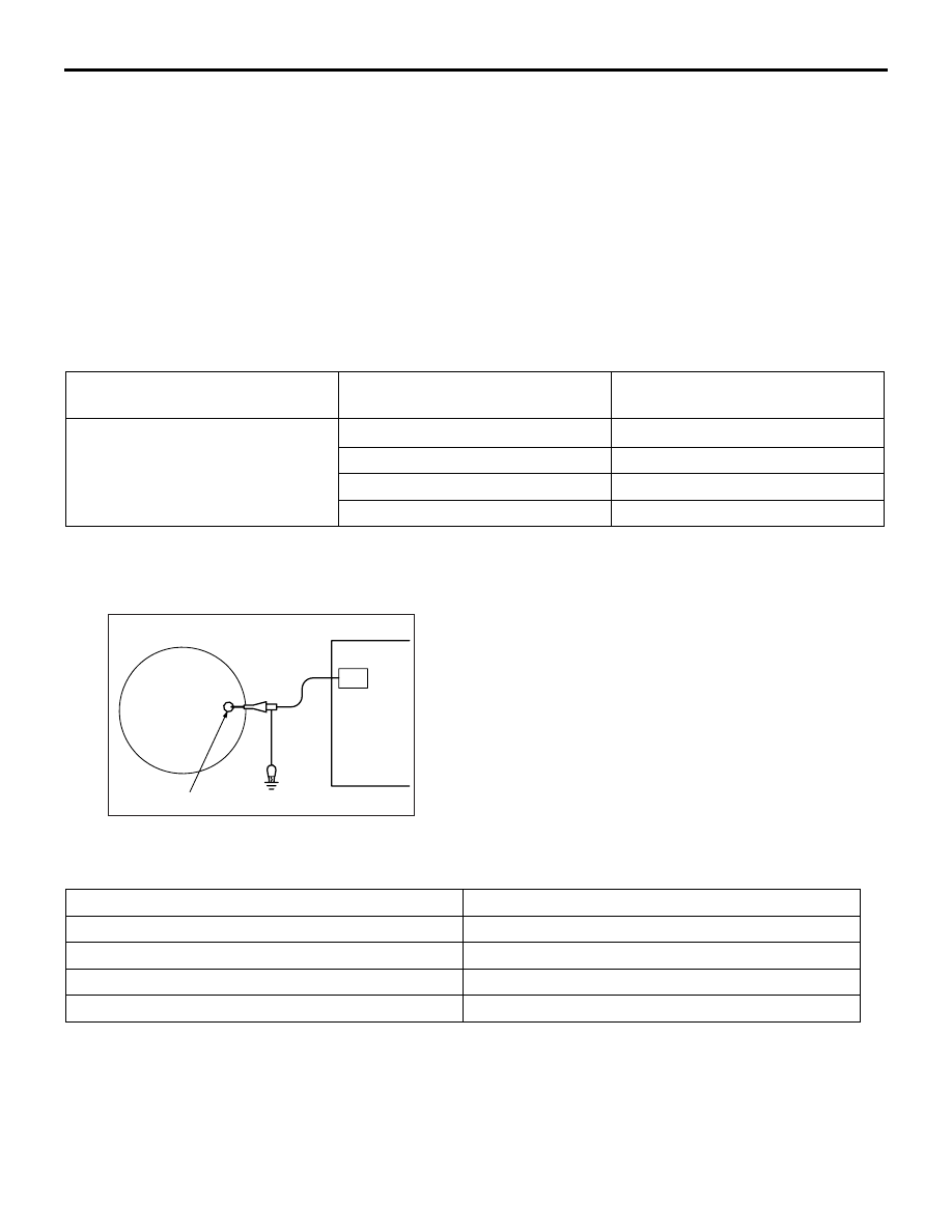
WAVEFORM CHECK USING AN OSCILLOSCOPE

M1161001201428

MEASUREMENT METHOD

AK701885

AC

CH1

"B" terminal

Alternator

Connect the oscilloscope special patterns pick-up to 
the alternator "B" terminal.

STANDARD WAVEFORM

Observation Conditions

Function

Special pattern

Pattern height

Variable

Variable knob

Adjust while viewing the waveform.

Pattern selector

Raster

Engine speed

Curb idle speed

AK701886AB

0.4

0.2

0

-0.2

-0.4

Voltage
at alternator
"B" terminal

Time

CHARGING SYSTEM

ENGINE ELECTRICAL

16-11

NOTE: 

AK701862

The voltage waveform of the alternator "B" terminal 
can undulate as shown in the illustration. This wave-
form is produced when the regulator operates 
according to fluctuations in the alternator load (cur-
rent), and is normal for the alternator. In addition, 

when the voltage waveform reaches an excessively 
high value (approximately 2 V or higher at idle), it 
often indicates an open circuit due to a brown fuse 
between alternator "B" terminal and battery, but not a 
defective alternator.

EXAMPLE OF ABNORMAL WAVEFORMS

NOTE: 

.

1. The size of the waveform patterns differs largely, depending on the adjustment of the variable knob on the 

oscilloscope.

2. Identification of abnormal waveforms is easier when there is a large output current (regulator is not oper-

ating). (Waveforms can be observed when the headlamps are illuminated.)

3. Check the conditions of the charging warning lamp (illuminated/not illuminated). Also, check the charging 

system totally.

Abnormal waveform

Problem cause

Except Euro 5

Euro 5

Example 1 

AK502669

Example 1 

AK703778

Open diode

Example 2 

AK502670

Example 2 

AK703780

Short in diode

Example 3 

AK502671

Example 3 

AK703781

Broken wire in 
stator coil

Example 4 

AK502672

Example 4 

AK703782

Short in stator 
coil

CHARGING SYSTEM

ENGINE ELECTRICAL

16-12

CHARGING SYSTEM

ENGINE ELECTRICAL

16-13

ALTERNATOR ASSEMBLY

REMOVAL AND INSTALLATION

M1161001403804

CAUTION

When the specified alternator is not used, each ECU would probably fail.

Pre-removal Operation
• Air Cleaner Assembly Removal (Refer to GROUP 15 − Air 

Cleaner ).

• Intercooler Inlet Air Hose Removal (Refer to GROUP 15 − 

Intercooler ) <Except Euro5>.

• Intercooler Inlet Air Hose Removal (Refer to GROUP 15 − 

Intercooler ) <Euro5>.

• A/C Compressor Drive Belt, Alternator and Power Steer-

ing Oil Pump Drive Belt Removal (Refer to GROUP 11A 

− 

Crankshaft Pulley ).

Post-installation Operation
• A/C Compressor Drive Belt, Alternator and Power Steer-

ing Oil Pump Drive Belt Installation (Refer to GROUP 11A 

− Crankshaft Pulley ).

• Intercooler Inlet Air Hose Installation (Refer to GROUP 15 

− Intercooler ) <Except Euro5>.

• Intercooler Inlet Air Hose Installation (Refer to GROUP 15 

− Intercooler ) <Euro5>.

• Air Cleaner Assembly Installation (Refer to GROUP 15 − 

Air Cleaner ).

• Alternator and Power Steering Oil Pump Drive Belt Ten-

sion Check (Refer to GROUP 11A 

− On-vehicle Service, 

Alternator and Power Steering Oil Pump Drive Belt Ten-

sion Check ).

• A/C Compressor Drive Belt Tension Check and Adjust-

ment (Refer to GROUP 11A 

− On-vehicle Service, A/C 

Compressor Drive Belt Tension Check and Adjustment ).

AC503001AC

2

23 ± 2 N·m

1

14 ± 4 N·m

3

44 ± 10 N·m

Removal steps 

1.

Alternator connector connection

2.

Alternator terminal connection

<<

A

>>

3.

Alternator assembly

Removal steps (Continued)


Content   ..  218  219  220  221   ..