Mitsubishi L200. Manual - part 219


  Index      Mitsubishi     Mitsubishi L200 - service repair manual 2012 year


Search            


Content   ..  217  218  219  220   ..


Mitsubishi L200. Manual - part 219


CHARGING SYSTEM

ENGINE ELECTRICAL

16-6

ON-VEHICLE SERVICE

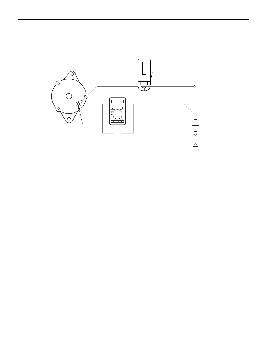
ALTERNATOR OUTPUT LINE VOLTAGE DROP TEST

M1161000900926

AK203361AD

Alternator

Ammeter (clamp-type)

Voltmeter (digital-type)

"B" terminal

Battery

This test determines whether the wiring from the 
alternator "B" terminal to the battery (+) terminal 
(including the fusible line) is in a good condition or 
not.
1. Always be sure to check the following before the 

test.

• Alternator installation

• Drive belt tension

(Refer to GROUP 11A 

− On-Vehicle Service − Alter-

nator and Power Steering Oil Pump Drive Belt 
Tension Check and Adjustment ). 

• Fusible link

• Abnormal noise from the alternator while the 

engine is running

2. Turn the ignition switch to the "LOCK" (OFF) 

position.

3. Disconnect the negative battery cable.
4. Connect a clamp-type DC test ammeter with a 

range of 0 

− 100 A to the alternator "B" terminal 

output wire.
NOTE: The way of disconnecting the alternator 
output wire and of connecting the ammeter is pos-
sibly not found the problem that the output current 
is dropping due to the insufficient connection 
between terminal "B" and the output wire.

5. Connect a digital-type voltmeter between the 

alternator "B" terminal and the battery (+) 
terminal. [Connect the (+) lead of the voltmeter to 
the "B" terminal and connect the (

−) lead of the 

voltmeter to the battery (+) cable].

6. Reconnect the negative battery cable.
7. Connect the M.U.T.-III or tachometer
8. Leave the hood open.
9. Start the engine.
10.With the engine running at 2,500 r/min, turn the 

headlamps and other lamps on and off to adjust 
the alternator load so that the value displayed on 
the ammeter is slightly above 30 A.
Adjust the engine speed by gradually decreasing 
it until the value displayed on the ammeter is 30 
A. Take a reading of the value displayed on the 
voltmeter at this time.

Limit: Maximum 0.3 V

NOTE: When the alternator output is high and the 
value displayed on the ammeter does not 
decrease until 30 A, set the value to 40 A. Read 
the value displayed on the voltmeter at this time. 
When the value range is 40 A, the limit is maxi-
mum 0.4 V.

CHARGING SYSTEM

ENGINE ELECTRICAL

16-7

11.If the value displayed on the voltmeter is above 

the limit value, there is probably a malfunction in 
the alternator output wire, so check the wiring 
between the alternator "B" terminal and the 
battery (+) terminal (including fusible link).
If a terminal is not sufficiently tight or if the 
harness has become discoloured due to 
overheating, repair and then test again.

12.After the test, run the engine at idle.
13.Turn off all lamps.
14.Turn the ignition switch to the "LOCK" (OFF) 

position.

15.Remove the M.U.T.-III or tachometer.
16.Disconnect the negative battery cable.
17.Disconnect the ammeter and voltmeter.
18.Connect the negative battery cable.

OUTPUT CURRENT TEST

M1161001002427

AKB00234

Alternator

Ammeter
(clamp-type)

Voltmeter

Battery

Ignition
switch-IG

AB

Charging 
warning lamp

Combination meter

Load

+

B

L

S

+

G

Engine-ECU

<Euro 5>

This test determines whether the alternator output 
current is normal.
1. Before the test, always be sure to check the 

following.

• Alternator installation

• Battery (Refer to GROUP 54A − Battery − On-

Vehicle Service 

− Battery Test .)

NOTE: The battery should be slightly discharged. 

The load needed by a fully-charged battery is 
insufficient for an accurate test.

• Drive belt tension

(Refer to GROUP 11A 

− On-Vehicle Service − Alter-

nator and Power Steering Oil Pump Drive Belt 
Tension Check and Adjustment .) 

• Fusible link

•  Abnormal noise from the alternator while the 

engine is running.

2. Turn the ignition switch to the "LOCK" (OFF) 

position.

3. Disconnect the negative battery cable.

CHARGING SYSTEM

ENGINE ELECTRICAL

16-8

CAUTION

Never use clips but tighten bolts and nuts to con-
nect the line. Otherwise loose connections (e.g. 
using clips) will lead to a serious accident 
because of high current.
4. Connect a clamp-type DC test ammeter with a 

range of 0 

− 100 A to the alternator "B" terminal 

output wire.
NOTE: The way of disconnecting the alternator 
output wire and of connecting the ammeter is pos-
sibly not found the problem that the output current 
is dropping due to the insufficient connection 
between terminal "B" and the output wire.

5. Connect a voltmeter with a range of 0 

− 20 V 

between the alternator "B" terminal and the earth 
[Connect the (+) lead of the voltmeter to the "B" 
terminal, and then connect the (

−) lead of the 

voltmeter to the earth].

6. Connect the negative battery cable.
7. Connect the M.U.T.-III or tachometer.
8. Leave the hood open.
9. Check that the reading on the voltmeter is equal 

to the battery voltage.
NOTE: If the voltage is 0 V, the cause is probably 
an open circuit in the wire or fusible link between 
the alternator "B" terminal and the battery (+) ter-
minal.

10.Turn the light switch on to turn on headlamps and 

then start the engine.

11.Immediately after setting the headlamps to high 

beam and turning the heater blower switch to the 
high revolution position, increase the engine 
speed to 2,500 r/min and read the maximum 
current output value displayed on the ammeter.

Limit: 70% of normal current output

NOTE: 

.

For the nominal current output, refer to the 
Alternator Specifications.

Because the current from the battery will soon 
drop after the engine is started, the above step 
should be carried out as quickly as possible in 
order to obtain the maximum current output 
value.

The current output value will depend on the 
electrical load and the temperature of the 
alternator body.

If the electrical load is small while testing, the 
specified level of current may not be output 
even though the alternator is normal. In such 
cases, increase the electrical load by leaving 
the headlamps turned on for some time to dis-
charge the battery or by using the lighting sys-
tem in another vehicle, and then test again.

The specified level of current also may not be 
output if the temperature of the alternator body 
or the ambient temperature is too high. In such 
cases, cool the alternator and then test again.

12.The reading on the ammeter should be above the 

limit value. If the reading is below the limit value 
and the alternator output wire is normal, remove 
the alternator from the engine and check the 
alternator.

13.Run the engine at idle after the test.
14.Turn the ignition switch to the "LOCK" (OFF) 

position.

15.Remove the M.U.T.-III or tachometer.
16.Disconnect the negative battery cable.
17.Disconnect the ammeter and voltmeter.
18.Connect the negative battery cable.

CHARGING SYSTEM

ENGINE ELECTRICAL

16-9

REGULATED VOLTAGE TEST

M1161001102457

AKB00235

+

+

AB

Battery

Ignition
switch-IG

Ammeter (clamp-type)

Load

Blue

MB991519

Voltmeter (digital-type)

Yellow

Red

Black

Alternator

Charging 
warning lamp

Combination meter

B

L

S

G

Engine-ECU

<Euro 5>

This test determines whether the voltage regulator 
correctly controlling the alternator output voltage.
1. Always be sure to check the following before the 

test.

• Alternator installation

• Check that the battery installed in the vehicle is 

fully charged.

(Refer to GROUP 54A 

− Battery − On-Vehicle Serv-

ice 

− Battery Test .)

• Drive belt tension

(Refer to GROUP 11A 

− On-Vehicle Service − Alter-

nator and Power Steering Oil Pump Drive Belt 
Tension Check and Adjustment .) 

• Fusible link

• Abnormal noise from the alternator while the 

engine is running

2. Turn the ignition switch to the "LOCK" (OFF) 

position.

3. Disconnect the negative battery cable.

4. Use the special tool Alternator test harness 

(MB991519) to connect a digital voltmeter 
between the alternator "S" terminal and earth 
[Connect the (+) lead of the voltmeter to the "S" 
terminal, and then connect the (

−) lead of the 

voltmeter to a secure earth or to the battery (

−) 

terminal].

5. Connect a clamp-type DC test ammeter to the 

alternator "B" terminal output wire.

6. Reconnect the negative battery cable.
7. Connect the M.U.T.-III or tachometer.
8. Turn the ignition switch to the "ON" position and 

check that the reading on the voltmeter is equal to 
the battery voltage.
NOTE: If the voltage is 0 V, the cause is probably 
an open circuit in the wire or fusible link between 
the alternator "S" terminal and the battery (+) ter-
minal.

9. Turn all lamps and accessories off.
10.Start the engine.
NOTE: Do not drive the vehicle after the engine 
starts.
11.Increase the engine speed to 2,500 r/min.


Content   ..  217  218  219  220   ..