Mitsubishi L200. Manual - part 209
THERMOSTAT
ENGINE COOLING
14-8
INSPECTION
M1141002500676
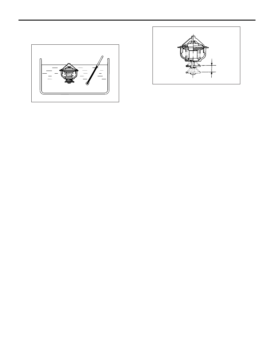
THERMOSTAT CHECK
ACX00400AB
1. Immerse the thermostat in water, and heat the
water while stirring. Check the thermostat valve
opening temperature.
Standard value: 82
± 2°C
ACX00401AC
Valve lift
2. Check that the amount of valve lift is at the
standard value when the water is at the full-
opening temperature.
NOTE: Measure the valve height when the ther-
mostat is fully closed, and use this measurement
to compare the valve height when the thermostat
is fully open.
Standard value:
Full-opening temperature: 95
°C
Amount of valve lift: 10 mm or more