Mitsubishi L200. Manual - part 205
GENERAL INFORMATION
FUEL SUPPLY
13B-2
GENERAL INFORMATION
M1135000100725
Fuel tank is mounted on the front of the rear axle to
reduce the shock at impact. A fuel cut valve, which
prevents fuel leakage when the vehicle banks or rolls
over, has been located inside the fuel tank for fewer
openings and hose bonding points on the fuel tank
top surface.
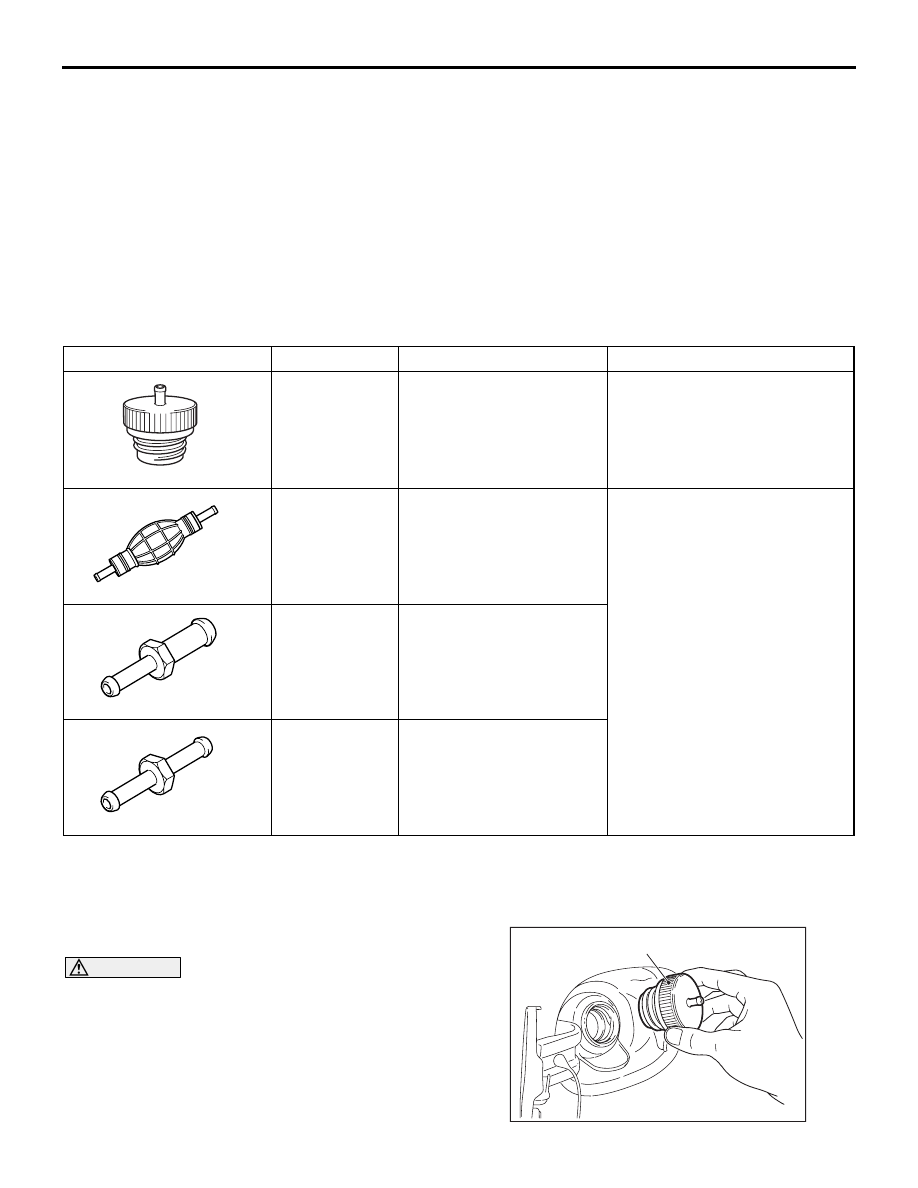
SPECIAL TOOLS
M1135000601143
Tool
Number
Name
Use
B992145
MB992145
Fuel leak check cap
Fuel leak check
B992264
MB992264
Fuel hand pump
Fuel draining
B992265
MB992265
Fuel hose adaptor A
B992266
MB992266
Fuel hose adaptor B
ON-VEHICLE SERVICE
FUEL LEAK CHECK OF FUEL TANK
M1135005900566
CAUTION
Always check the fuel leak of fuel tank with the
vehicle loaded. If it is checked with the fuel tank
removed, the fuel tank may be damaged.
AC600149
MB992145
AC