Mitsubishi L200. Manual - part 200


  Index      Mitsubishi     Mitsubishi L200 - service repair manual 2012 year


Search            


Content   ..  198  199  200  201   ..


Mitsubishi L200. Manual - part 200


ON-VEHICLE SERVICE

DIESEL FUEL

13A-596

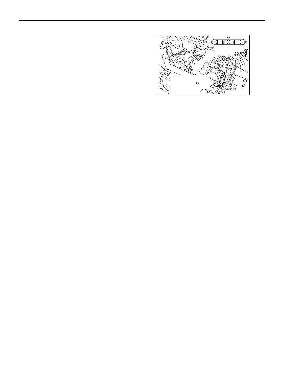
THROTTLE VALVE CONTROL SERVO 
CHECK

M1133010700283

OPERATION CHECK

1. Remove the air intake hose from the throttle body.
2. Turn the ignition switch to "ON" position.
3. Make sure that the throttle valve is open.
4. Turn the ignition switch to "OFF" position.

CHECK THE COIL RESISTANCE

1. Disconnect the electronic - controlled throttle 

valve connector.

2. Measure resistance between terminal No. 5 and 

No. 6 at the throttle valve control servo connector.

Standard value: 0.3 

 100  (at 20 °C)

3. If resistance is outside the standard value, replace 

the throttle body assembly.

AK501458

6

1 2 3 4 5

AB

Equipment side 
connector

Electronic-controlled 
throttle valve 
(incorporating throttle 
position sensor)

FUEL INJECTOR

DIESEL FUEL

13A-597

FUEL INJECTOR

REMOVAL AND INSTALLATION

M1133009400299

<Except Euro5>

Pre-removal Operation
• Inlet Manifold Removal (Refer to GROUP 15 − Inlet Mani-

fold ).

• Fuel Injection Pipe Removal (Refer to 

P.13A-604

).

Post-installation Operation
• Fuel Injection Pipe Installation (Refer to 

P.13A-604

).

• Inlet Manifold Installation (Refer to GROUP 15 − Inlet 

Manifold ).

AC502869AE

1

17

16

15

14

10

11

11

10

6

13

N

3

10 ± 2 N·m

10 ± 2 N·m

15 ± 2 N·m

12

15 ± 2 N·m

7

N

9

N

3.0 ± 1.0 N·m to


10 ± 2 N·m

5

N

18

N

4

N

10 ± 1 N·m to


+120˚ – +125˚

8

N

13

N

(Engine oil)

2

FUEL INJECTOR

DIESEL FUEL

13A-598

Removal steps 

When the fuel injector is replaced, 
register the injector identification 
code and perform the fuel injection 
learning (Refer to GROUP 00 

− 

Precautions before Service, What 
the Common Rail Engine Learns ) 
<Installation only>.

1.

Breather hose connection

2.

Harness bracket

3.

Timing belt front upper cover

>>

D

<< 4.

Oil seal

>>

D

<< 5.

Oil seal

<<

A

>> >>

C

<< 6.

Rocker cover assembly

7.

Rocker cover gasket A

8.

Rocker cover gasket B

9.

Rocker cover gasket C

>>

B

<< 10. Semi-circular packing

>>

A

<< 11. Eye bolt

>>

A

<< 12. Fuel leakage pipe

>>

A

<< 13. Fuel leak-off gasket

>>

A

<< 14. Injector holder bolt

>>

A

<< 15. Injector supporter

>>

A

<< 16. Pivot boss

>>

A

<< 17. Fuel injector

>>

A

<< 18. Nozzle gasket

Removal steps (Continued)

FUEL INJECTOR

DIESEL FUEL

13A-599

<Euro5>

AC805674 AD

1

19

18

17

16

12

13

13

12

8

15

N

4

10 ± 2 N·m

10 ± 2 N·m

15 ± 2 N·m

14

15 ± 2 N·m

9

N

11

N

3.0 ± 1.0 N·m to


10 ± 2 N·m

6

N

20

N

5

N

10 ± 1 N·m to


+120˚ – +125˚

10

N

15

N

(Engine oil)

2

3

7

23 ± 6 N·m

Removal steps 

When the fuel injector is replaced, 
register the injector identification 
code and perform the fuel injection 
learning (Refer to GROUP 00 

− 

Precautions before Service, What 
the Common Rail Engine Learns ) 
<Installation only>.

1.

Breather hose connection

2.

Harness bracket

3.

Solenoid valve and harness 
bracket assembly

4.

Timing belt front upper cover

>>

D

<< 5.

Oil seal

>>

D

<< 6.

Oil seal

7.

Vacuum pipe and hose assembly 
connection

<<

A

>> >>

C

<< 8.

Rocker cover assembly

9.

Rocker cover gasket A

10. Rocker cover gasket B
11. Rocker cover gasket C

>>

B

<< 12. Semi-circular packing

>>

A

<< 13. Eye bolt

>>

A

<< 14. Fuel leakage pipe

>>

A

<< 15. Fuel leak-off gasket

>>

A

<< 16. Injector holder bolt

>>

A

<< 17. Injector supporter

Removal steps (Continued)


Content   ..  198  199  200  201   ..