Mitsubishi L200. Manual - part 201


  Index      Mitsubishi     Mitsubishi L200 - service repair manual 2012 year


Search            


Content   ..  199  200  201  202   ..


Mitsubishi L200. Manual - part 201


FUEL INJECTOR

DIESEL FUEL

13A-600

REMOVAL SERVICE POINT

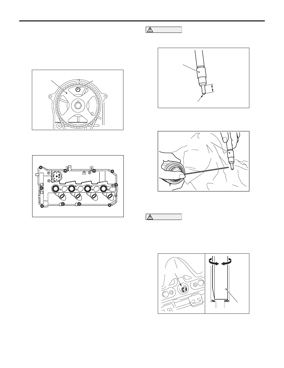
<<A>> ROCKER COVER ASSEMBLY REMOVAL

1. Turn the crankshaft clockwise, and remove the 

timing belt rear cover mounting bolts shown in the 
figure from the gap of the camshaft sprocket.

2. In the order shown in the figure, loosen the rocker 

cover assembly mounting bolts, and then remove 
the rocker cover assembly.

INSTALLATION SERVICE POINTS

>>A<< NOZZLE GASKET/FUEL INJECTOR/PIVOT 
BOSS/INJECTOR SUPPORTER/INJECTOR 
HOLDER BOLT/FUEL LEAK-OFF GASKET/FUEL 
LEAKAGE PIPE/EYE BOLT INSTALLATION
1. Clean the fuel injector assembly (nozzle) and the 

cylinder head (fuel injector insertion hole) by 
following the procedure below.

CAUTION

Do not clean the injection part of the nozzle with 
a resin spatula.

(1) Using a resin spatula, scrape off the carbon 

deposit on the fuel injector nozzle side face 
("A" shown in the figure).

(2) Spray the carburetor cleaner (MZ100139) or 

equivalent to the nozzle side face ("A" shown 
in the figure).

CAUTION

Do not touch the injection part of the nozzle with 
hand or wipe it with a rag.

(3) Leave the injection part for a while until the 

carbon deposit melts down, and then blow air 
to the injection part.

(4) Insert special tool ornament remover 

(MB990784) to the cylinder head (fuel injector 
insertion hole) with turning the special tool as 
shown, and scrape off the carbon deposit.

>>

A

<< 18. Pivot boss

>>

A

<< 19. Fuel injector

>>

A

<< 20. Nozzle gasket

Removal steps (Continued)

AC502870AB

Timing belt rear cover
mounting bolt

Camshaft sprocket

AC502871

3

AB

1

2

4

5

6

7

8

9

10

AC900270 AB

Fuel injector

A: Nozzle side face

Injection part of the nozzle

AC900203

Fuel injector

AB

AC900204

MB990784

Cylinder head

AB

FUEL INJECTOR

DIESEL FUEL

13A-601

CAUTION

In order to prevent carbon from adhering to the 
inner surface of the cylinder, blow air with the 
piston in the TDC position.

(5) Remove the special tool, and blow off the 

carbon deposit on the cylinder head (fuel 
injector insertion hole) by air.

(6) Check that there is no carbon deposit 

remaining on the contact surface of the fuel 
injector nozzle gasket.

NOTE: Repeat step 4 to step 6 several times 
until the carbon deposit is completely removed.

2. Install the nozzle gasket, fuel injector, pivot boss, 

and injector supporter to the cylinder head as 
shown in the figure.

3. Apply a small amount of engine oil to the seat 

surface and thread of injector holder bolt, and 
then temporarily tighten the bolt to the cylinder 
head.

4. Set the fuel leak-off gasket to the fuel leakage 

pipe, and temporarily tighten to the fuel injector 
and to the cylinder head using the eye bolt.

5. Tighten the eye bolt of the fuel injector side to the 

specified torque.

Tightening torque: 15 

± 2 Nm

6. Tighten the eye bolt of the cylinder head side to 

the specified torque.

Tightening torque: 15 

± 2 Nm

7. Tighten the injector holder bolt to the specified 

torque.

Tightening torque: 10 

± 1 Nm

CAUTION

• If the bolt is tightened less than the specified 

lower limit of 120

°, the bolt may become 

loose. Be sure to tighten correctly.

• If the bolt is tightened in excess of the speci-

fied upper limit of 125

°, loosen the nut com-

pletely and repeat the entire procedures.

8. Using special tool angle gauge (MB991614), 

tighten the injector holder bolt in the illustrated 
sequence by a further 120

° to 125°.

>>B<< SEMI-CIRCULAR PACKING 
INSTALLATION

Apply specified sealant to portions indicated in illus-
tration.

Specified sealant: Three bond 1217G or 
equivalent

NOTE: Install the semi-circular packing immediately 
after applying sealant.

AC502872 AB

Injector holder bolt

Injector supporter

Pivot boss

Fuel injector

Nozzle
gasket

AC502873AB

MB991614

AC502874AB

Semi-circular packing

FUEL INJECTOR

DIESEL FUEL

13A-602

>>C<< ROCKER COVER ASSEMBLY 
INSTALLATION

1. Apply specified sealant to portions indicated in 

illustration.

Specified sealant: Three bond 1217G or 
equivalent

NOTE: Install the rocker cover assembly immedi-
ately after applying sealant.
2. Install the rocker cover assembly to the cylinder 

head.

3. Tighten the rocker cover assembly mounting bolts 

to the specified torque in the order shown in the 
figure.

Tightening torque: 3.0 

± 1.0 Nm

CAUTION

After the installation, until a sufficient period of 
time (one hour or more) elapses, do not apply the 
oil or water to the sealant application area or 
start the engine.
4. Tighten the rocker cover assembly mounting bolts 

to the specified torque in the order shown in the 
figure again.

Tightening torque: 10 

± 2 Nm

>>D<< OIL SEAL INSTALLATION

Apply engine oil to the oil seal outer surface and 
drive in with a socket wrench.

AC502875AB

Semi-
circular
packing

Cylinder head

10mm

10mm

AC502871

8

AC

1

9

7

6

5

4

3

2

10

AC502876

(Engine oil)

AB

Rocker cover

Socket wrench

Oil seal

AC502877

(Engine oil)

AB

Rocker cover

Socket wrench

Oil seal

COMMON RAIL AND SUPPLY PUMP

DIESEL FUEL

13A-603

COMMON RAIL AND SUPPLY PUMP

REMOVAL AND INSTALLATION

M1133009600389

CAUTION

• The reinstallation histories of the removed fuel injection pipe and fuel supply pump pipe are up to 

five times. To count how many times the fuel injection pipe and fuel supply pump pipe are rein-
stalled, record the number of the reinstallation histories on the service booklet by adding this lat-
est number of the histories, which is usually "1", to the previous one. Use a new fuel injection pipe 
or fuel supply pump pipe when the total reinstallation history numbers reach five times, or when 
the fuel injector assembly, common rail assembly or supply pump assembly is replaced. In this 
case, record " a new fuel injection pipe or fuel supply pump pipe, the number of the reinstallation 
histories is zero" on the service booklet.

• If a fuel leak is present in the fuel injection pipe and fuel supply pump pipe once, do not reuse it 

and replace with a new one.

• If the fuel injector assembly, common rail assembly or supply pump assembly is replaced, the 

contact surface (seal surface) between the fuel injection pipe and fuel supply pump pipe, and the 
other side component is changed, do not reuse the fuel injection pipe and fuel supply pump pipe 
and replace with a new one.

• When the injection pipe is reinstalled, confirm there is no foreign material on the seal surface or in 

the pipe and then install it not to deviate from the axis, fitting the seal surface.

<Except Euro5>

Pre-removal Operation
• Inlet Manifold Removal (Refer to GROUP 15 − Inlet Mani-

fold ).

Post-installation Operation
• Inlet Manifold Installation (Refer to GROUP 15 − Inlet 

Manifold ).

• Fuel Line Leak Check (Refer to 

P.13A-590

).

AC502865

12

1

20 ± 2 N·m

3

2

5

7

9

N

11

10

8

N

17 ± 2 N·m

10 ± 2 N·m

10 ± 2 N·m

10 ± 2 N·m

10 ± 2 N·m

10 ± 2 N·m

35 ± 5 N·m

35 ± 5 N·m

24 ± 4 N·m

24 ± 4 N·m

64 ± 5 N·m

AG

6

6

N

4

35 ± 5 N·m

35 ± 5
N·m

35 ± 5 N·m


Content   ..  199  200  201  202   ..