Mitsubishi L200. Manual - part 198


  Index      Mitsubishi     Mitsubishi L200 - service repair manual 2012 year


Search            


Content   ..  196  197  198  199   ..


Mitsubishi L200. Manual - part 198


ON-VEHICLE SERVICE

DIESEL FUEL

13A-588

ON-VEHICLE SERVICE

EVACUATION OF WATER FROM FUEL 
FILTER

M1133001200406

<Vehicles with steel fuel filter case>

Water is in the fuel filter when fuel filter indicator 
lamp illuminates. Evacuate water by the following 
procedures.

1. Loosen the drain plug.
2. After water is evacuated by using an hand pump, 

tighten the drain plug.

<Vehicles with plastic fuel filter case>

Water is in the fuel filter when fuel filter indicator 
lamp illuminates. Evacuate water by the following 
procedures.

1. Loosen the drain plug.
2. After water is evacuated by using an hand pump, 

tighten the drain plug.

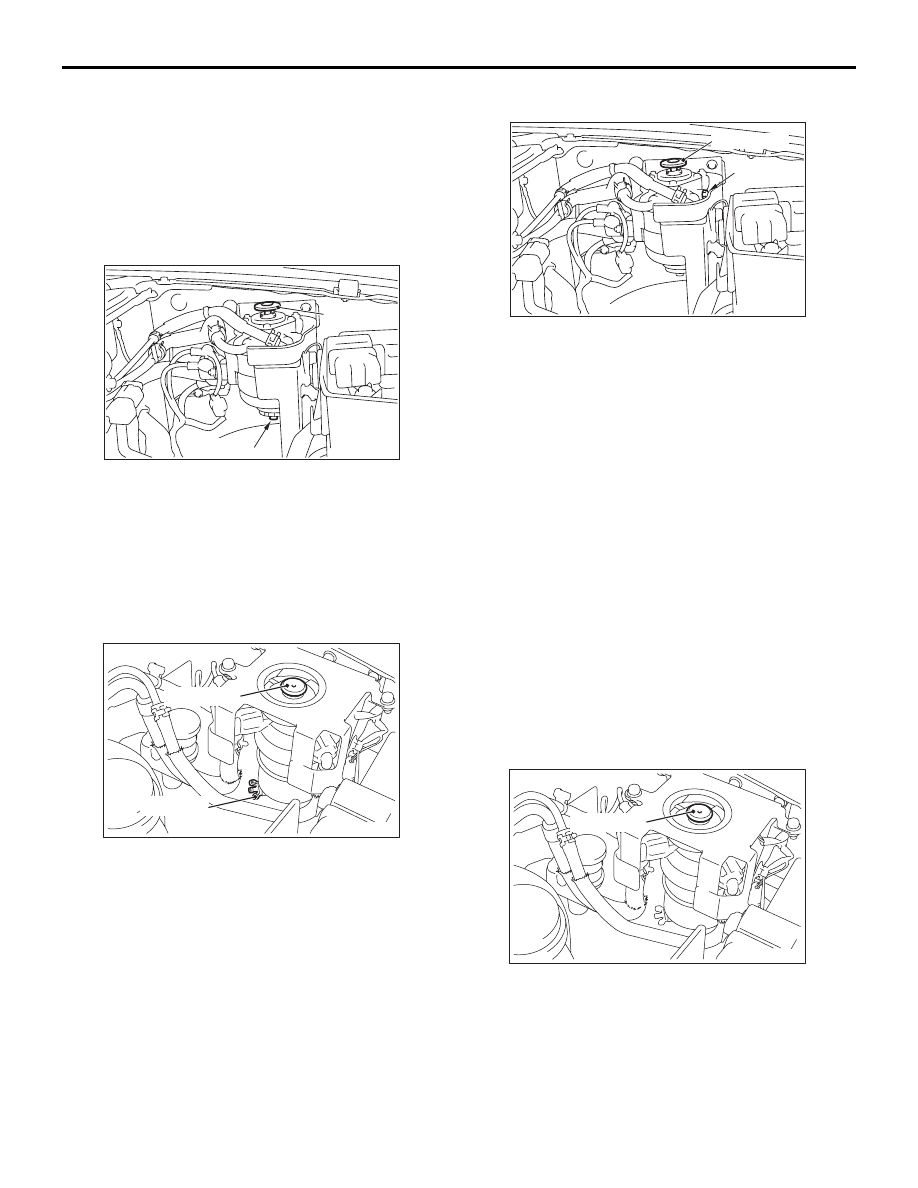
EVACUATION OF AIR FROM FUEL LINE

M1133001300362

<Vehicles with steel fuel filter case>

When the following service work(s) is done, refill the 
fuel tank and then evacuate air from the fuel line.

• Fuel hose or pipe is removed

• Fuel filter is replaced

• Fuel injector is removed

• If necessary for access, fuel is drained from the 

fuel tank.

1. Remove the fuel filter air plug and O-ring 

<Vehicles with air plug>.

2. Cover the circumference of the air plug hole with 

cloth and use a hand pump repeatedly until no 
bubbles come out of the air plug hole <Vehicles 
with air plug>.

3. Replace the air plug and O-ring with a new one. 

Tighten the air plug to the specified torque 
<Vehicles with air plug>.

Tightening torque: 5.0 

± 1.0 Nm

4. Repeat until the hand pump operation becomes 

stiff.

<Vehicles with plastic fuel filter case>

When the following service work(s) is done, refill the 
fuel tank and then evacuate air from the fuel line.

• Fuel hose or pipe is removed

• Fuel filter is replaced

• Fuel injector is removed

• If necessary for access, fuel is drained from the 

fuel tank.

1. Repeat until the hand pump operation becomes 

stiff.

FUEL FILTER REPLACEMENT

M1133010800387

<Vehicles with steel fuel filter case>

Refer to GROUP 13B 

− Fuel Filter .

AC506328AB

Hand pump

Drain plug

ACB01923AB

Hand pump

Drain plug

AC503662AB

Hand pump

Air plug

ACB01924AB

Hand pump

ON-VEHICLE SERVICE

DIESEL FUEL

13A-589

<Vehicles with plastic fuel filter case>

Refer to GROUP 13B 

− Fuel Filter .

FUEL LINE LEAK CHECK

M1133011700189

NOTE: Since the fuel injection pipe connection on 
the fuel injector assembly side is located inside the 
engine (rocker cover), visual check for fuel leak can-
not be performed. Due to this, use the oil leak detec-
tion agent to check for fuel leak. As for other fuel 
injection pipe and the fuel supply pump pipe connec-
tion, visually check for fuel leak.
NOTE: The oil leak detection agent detects oil leak 
by colour change when it is applied to the area to be 
checked. For details on how to use the product, refer 
to the instruction manual.
1. Remove the engine cover assembly upper (Refer 

to GROUP 11A 

− Engine Assembly ).

CAUTION

Degrease the area between the flare nut and the 
pipe of the fuel injection pipe by fully spraying 
the parts cleaner.

2. Carefully degrease the flare nut at the fuel injector 

assembly side of the fuel injection pipe with parts 
cleaner (MZ100387) or equivalent.

3. If the parts cleaner remains in the area between 

the flare nut for connection and the fuel injection 
pipe, the oil leak detection agent detects that 
there is a fuel leak. Therefore, use an air gun to 
blow off the remaining parts cleaner and fully dry 
the degreased area.

4. Apply the oil leak detection agent to the flare nut 

and the pipe of the fuel injection pipe.
NOTE: It is easy to detect the oil leak when the oil 
leak detection agent is dry enough because the 
colour changes clearly. Use a dryer to dry the oil 
leak detection agent when it is hard to dry.

CAUTION

Before connecting or disconnecting the M.U.T.-
III, turn the ignition switch to the "LOCK" (OFF) 
position.

5. Ensure that the ignition switch is at the "LOCK" 

(OFF) position.

6. Start up the personal computer.
7. Connect special tool M.U.T.-III USB cable 

(MB991827) to V.C.I. (MB991824) and the 
personal computer.

8. Connect special tool M.U.T.-III main harness A 

(MB991910) to the V.C.I.

ACA00283 AC

Fuel

injection

pipe

Rocker cover

Flare nut

AC509179

AB

Diagnosis

connector

MB991827

MB991824 

MB991910

<LH drive vehicles>

AC501413AC

Diagnosis

connector

MB991827

MB991824 

MB991910

<RH drive vehicles>

ON-VEHICLE SERVICE

DIESEL FUEL

13A-590

9. Connect the M.U.T.-III main harness A to the 

diagnosis connector of the vehicle.

10.Turn the V.C.I. power switch to the "ON" position.

NOTE: When the V.C.I. is energized, the V.C.I. 
indicator lamp will be illuminated in a green col-
our.

11.Start the M.U.T.-III system on the personal 

computer and turn the ignition switch to the "ON" 
position.

12.Start the engine, and let it run at idle.
13.Select "MPI/GDI/DIESEL" from System select 

Screen of the M.U.T.-III.

14.Select "SPECIAL FUNCTION" from MPI/GDI/

DIESEL Screen.

15.Select "FUEL LEAKAGE CHECK" from Test 

Screen. Carry out the fuel leakage check (during 
the test, the engine speed and the fuel pressure is 
2,000 r/min and 180 MPa for 20 seconds 
respectively) five times in a row (20 seconds 

× 5 

times = 100 seconds).

16.Turn the ignition switch to the "LOCK" (OFF) 

position, and stop the engine.

17.Disconnecting the M.U.T.-III is the reverse of the 

connecting sequence.

18.Check the colour change of the oil leak detection 

agent at the flare nut and pipe of the fuel injection 
pipe to check if the fuel is leaking from the fuel 
injection pipe connection at the fuel injector 
assembly side.

19.Visually check other fuel line connections for fuel 

leak.

20.If the fuel is leaking, replace the fuel injection pipe 

and the fuel supply pump pipe. (Refer to 

P.13A-

604

.)

21.If the fuel is not leaking, wipe off the oil leak 

detection agent using parts cleaner (MZ100387) 
or equivalent completely.

22.Install the engine cover assembly upper (Refer to 

GROUP 11A 

− Engine Assembly ).

COMPONENT LOCATION

M1133004700660

Name

Symbol

Name

Symbol

Accelerator pedal position sensor

V

1st and 2nd rail switch <M/T>

R

A/C compressor relay

Q

Fuel filter pressure switch <Vehicle for 
Russia and Morocco> 

I

A/C switch

Y

Fuel temperature sensor

N

Air flow sensor (incorporating intake air 
temperature sensor No. 1)

J

Glow control unit <Euro5>

I

Back-up lamp switch <M/T>

S

Glow plug relay <Except Euro5>

I

Battery current sensor (incorporating 
battery temperature sensor) <Euro5>

P

Injector

C

Camshaft position sensor

E

Intake air temperature sensor No. 2 
<Except Euro5>

G

Crank angle sensor

M

Manifold absolute pressure sensor

G

Diagnosis connector

X

No. 1 exhaust gas temperature sensor 
<Euro5>

B

DPF lamp <Euro5>

W

No. 2 exhaust gas temperature sensor 
(catalyst temperature) <Euro5>

a

EGR gas temperature sensor <Euro5>

D

No. 3 exhaust gas temperature sensor 
(DPF temperature) <Euro5>

b

EGR valve (DC motor) (incorporating 
EGR valve position sensor)

F

Power steering fluid pressure switch

K

Electronic-controlled throttle valve 
(incorporating throttle position sensor)

G

PTC heater relay 1,2 <Vehicles with PTC 
heater>

H

Engine-ECU

Z

Rail pressure sensor

E

Engine control relay

Q

Starter relay

Q

ON-VEHICLE SERVICE

DIESEL FUEL

13A-591

Engine coolant temperature sensor

O

Suction control valve

L

Engine warning lamp (check engine 
lamp)

U

Variable geometry control solenoid valve 
<Euro5>

L

Exhaust differential pressure sensor 
<Euro5>

A

Vehicle speed sensor <2WD-M/T, 4WD> T

Name

Symbol

Name

Symbol

AKB00282

J

N

L

M

K

O

P

Q

AB

F

B

E

G

A

C

D

I

H


Content   ..  196  197  198  199   ..