Mitsubishi L200. Manual - part 180


  Index      Mitsubishi     Mitsubishi L200 - service repair manual 2012 year


Search            


Content   ..  178  179  180  181   ..


Mitsubishi L200. Manual - part 180


TROUBLESHOOTING

DIESEL FUEL

13A-516

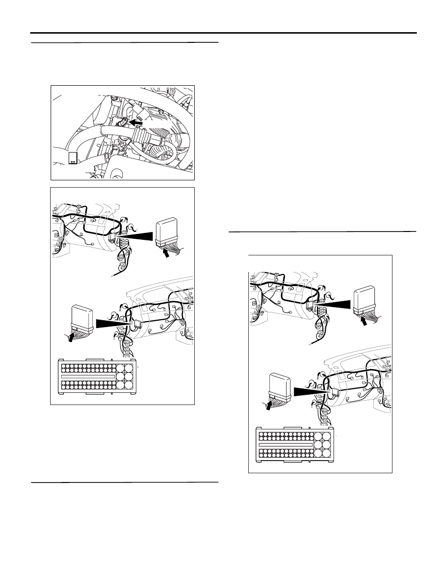
STEP 6. Check harness between A-134 (terminal 
No. 1) power steering fluid pressure switch 
connector and C-103 (terminal No. 127) engine-
ECU connector.

NOTE: Before checking harness, check intermediate 
connectors A-27 and A-115, and repair if necessary.

• Check output line for short circuit.

Q: Is the check result normal?

YES : 

Go to Step 7 .

NO : 

Repair the harness wire.

STEP 7. M.U.T.-III data list

• Refer to Data List Reference Table 

P.13A-542

.

a. Item 75: Power steering fluid pressure switch

Q: Is the check result normal?

YES : 

Intermittent malfunction (Refer to GROUP 

00 

− How to Use Troubleshooting/

Inspection Service Points 

− How to Cope 

with Intermittent Malfunctions ). 

NO : 

Replace the engine-ECU. When the engine-
ECU is replaced, write the chassis number 
(Refer to GROUP 00 

− Precautions Before 

Service 

− How to Perform Chassis Number 

Writing ). After replacing the engine-ECU, 
register the injector identification code and 
learn fuel injection (Refer to GROUP 00 

− 

Precautions Before Service 

− What The 

Common Rail Engine Learns ). After 
registering the injector identification code, 
the vehicle equipped with the DPF carries 
out the forcible DPF regeneration. (Refer to 
GROUP 17 

− Emission Control − Diesel 

Particulate Filter (DPF) System 

− Forcible 

DPF Regeneration ).

STEP 8. Perform voltage measurement at C-103 
engine-ECU connector.

• Measure engine-ECU terminal voltage.

• Engine: Idling

• Voltage between terminal No. 127 and earth.

OK: 

System voltage (Steering wheel: Stationary)
1 V or less (Steering wheel: Turned)

Q: Is the check result normal?

AK501383

1

Harness side 
connector

Connector: A-134

A-134 (B)

AB

AKA00090

101

102

103

104

105

106

107

108

109

110

111

112

113

114

115

118

119

120

121

122

123

124

125

126

127

128

129

130

131

132

133

134

135

136

137

138

139

140

141

142

143

146

147

148

149

150

151

152

153

154

155

156

157

158

117

145

116

144

C-103 (B)

C-103 (B)

<R.H. drive vehicles>

Harness side connector

<L.H. drive vehicles>

Connector: C-103

AB

TROUBLESHOOTING

DIESEL FUEL

13A-517

YES : 

Go to Step 11 .

NO : 

Go to Step 9 .

STEP 9. Connector check: C-103 engine-ECU 
connector

Q: Is the check result normal?

YES : 

Go to Step 10 .

NO : 

Repair or replace.

STEP 10. Check harness between A-134 (terminal 
No. 1) power steering fluid pressure switch 
connector and C-103 (terminal No. 127) engine-
ECU connector.

NOTE: Before checking harness, check intermediate 
connectors A-27 and A-115, and repair if necessary.

• Check output line for damage.

Q: Is the check result normal?

YES : 

Replace the power steering fluid pressure 

switch.

NO : 

Repair the harness wire.

AKA00090

101

102

103

104

105

106

107

108

109

110

111

112

113

114

115

118

119

120

121

122

123

124

125

126

127

128

129

130

131

132

133

134

135

136

137

138

139

140

141

142

143

146

147

148

149

150

151

152

153

154

155

156

157

158

117

145

116

144

C-103 (B)

C-103 (B)

<R.H. drive vehicles>

Harness side connector

<L.H. drive vehicles>

Connector: C-103

AB

AK501383

1

Harness side 
connector

Connector: A-134

A-134 (B)

AB

AKA00090

101

102

103

104

105

106

107

108

109

110

111

112

113

114

115

118

119

120

121

122

123

124

125

126

127

128

129

130

131

132

133

134

135

136

137

138

139

140

141

142

143

146

147

148

149

150

151

152

153

154

155

156

157

158

117

145

116

144

C-103 (B)

C-103 (B)

<R.H. drive vehicles>

Harness side connector

<L.H. drive vehicles>

Connector: C-103

AB

TROUBLESHOOTING

DIESEL FUEL

13A-518

STEP 11. Connector check: C-103 engine-ECU 
connector

Q: Is the check result normal?

YES : 

Go to Step 7 .

NO : 

Repair or replace.

AKA00090

101

102

103

104

105

106

107

108

109

110

111

112

113

114

115

118

119

120

121

122

123

124

125

126

127

128

129

130

131

132

133

134

135

136

137

138

139

140

141

142

143

146

147

148

149

150

151

152

153

154

155

156

157

158

117

145

116

144

C-103 (B)

C-103 (B)

<R.H. drive vehicles>

Harness side connector

<L.H. drive vehicles>

Connector: C-103

AB

TROUBLESHOOTING

DIESEL FUEL

13A-519

Inspection Procedure 25: Glow System <Except Euro5>

OPERATION

• The engine-ECU controls the glow plug relay and 

glow indicator lamp based on the signal of the 
engine coolant temperature sensor in order to 
easily start the engine at the cool condition.

PROBABLE CAUSES

• Failed glow control relay

• Failed glow plug

AKA00122

1

1

1

2

1

39

37

40 41 42

38

31

35

34

33

36

32

60

58

61 62 63 64

59

51

55

54

53

56 57

52

1

2

3

4

5 6 7 8 9

10 1112 13 14 15 16 17 18 19 20 21 22 23 24

25 26

27 28 29 30 31 32 33 34 35 36 37 38 39 40 41 42

49 50 51 52 53 54 55 56 57 58 59 60 61 62 63 64 65 66 67 68 69 70 71 72

43 44 45 46 47 48

73 74 75 76 77 78 79 80 81 82 83 84 85 86 87 88 89 90 91 92 93 94 95 96

J/C (5)

C-132

Glow System Circuit

20

1

1

A-111

1

A-11

A-11

A-111

2

B-R

W-R

W

R

1

22

24

C-53*¹ or
C-35*²

51

C-111

36

15

12

6

C-209

4

15

7.5A

C-207

C-112

C-111

MU801586

L

L

B-W

B-W

J/B

L-B

Engine-ECU

Combination
meter

Glow
plugs

Glow
plug
relay

A-06

C-105

Wire colour code
B: Black  LG: Light green  G: Green  L: Blue  W: White  Y: Yellow  SB: Sky blue  BR: Brown  O: Orange  GR: Grey
R: Red  P: Pink  V: Violet  PU: Purple  SI: Silver

C-112

A-112

MU802601

Fusible link

Engine control relay

Ignition switch (IG1)

OFF

ON

Glow

NOTE

*1: L.H. drive vehicles
*2: R.H. drive vehicles

24

AB


Content   ..  178  179  180  181   ..